Rice noodle raw material washing device convenient for discharging
A technology for cleaning devices and raw materials, applied in the directions of cleaning methods, cleaning methods and utensils, chemical instruments and methods using liquids, etc., which can solve problems such as workers being unable to observe processing conditions, unfavorable material discharge work, and affecting ground environmental hygiene.
- Summary
- Abstract
- Description
- Claims
- Application Information
AI Technical Summary
Problems solved by technology
Method used
Image

Examples
Embodiment Construction
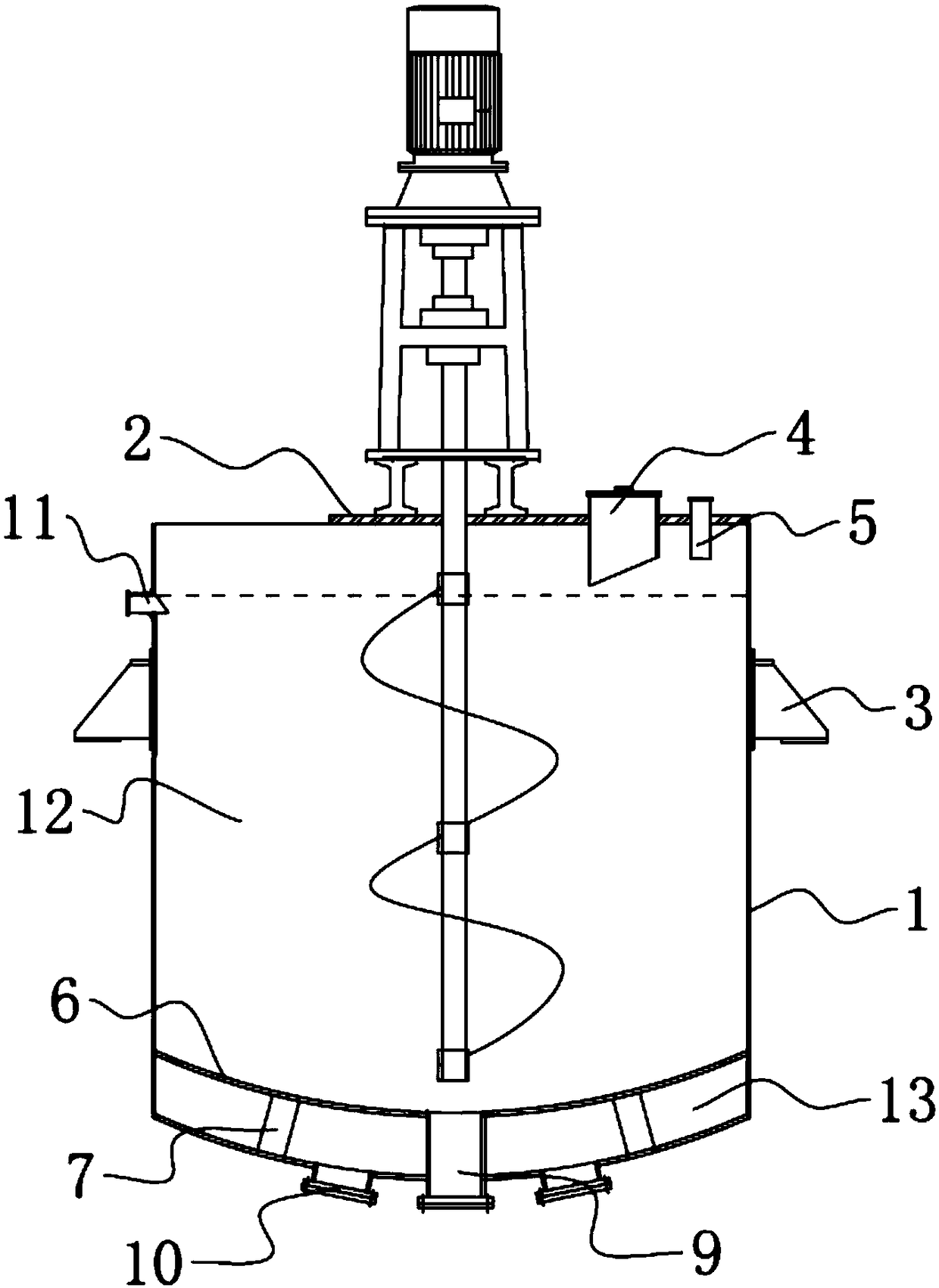
[0019] Through the following examples, combined with the attached Figure 1-3 , the technical solution of the present invention will be further specifically described.
[0020] A cleaning device for rice flour raw materials that is convenient for discharging, comprising a steel bucket body 1, wherein a plurality of sets of support seats 3 are welded on the outer side wall of the upper half of the barrel body 1, by fixing the plurality of sets of support seats 3 on the support platform The barrel body 1 is suspended in the air so that it does not come into contact with the wet ground to ensure the dryness of the bottom. At the same time, the support seat 3 is locked on the support platform by the anchor bolts to prevent its displacement or movement.
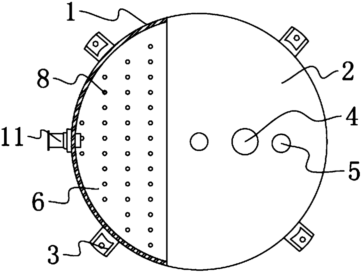
[0021] Wherein, a bow-shaped steel cover plate 2 is installed on the right side of the top of the barrel body 1. The cover plate 2 is locked on the top of the side wall of the barrel body 1 by bolts, and workers can see through th...
PUM
| Property | Measurement | Unit |
|---|---|---|
| Minimum diameter | aaaaa | aaaaa |
Abstract
Description
Claims
Application Information
 - R&D
- Intellectual Property
- Life Sciences
- Materials
- Tech Scout
- Unparalleled Data Quality
- Higher Quality Content
- 60% Fewer Hallucinations
Browse by: Latest US Patents, China's latest patents, Technical Efficacy Thesaurus, Application Domain, Technology Topic, Popular Technical Reports.
© 2025 PatSnap. All rights reserved.Legal|Privacy policy|Modern Slavery Act Transparency Statement|Sitemap|About US| Contact US: help@patsnap.com