
Gear shaft part assembling mechanism convenient for press-in of short shaft

A technology of parts assembly and short shaft, which is applied in the field of gear shaft parts assembly mechanism, can solve the problems of high degree of damage to the gear shaft, affect the assembly effect, and inconsistent installation quality, so as to improve the adaptability range, good press-in effect, and improve the effect Effect

Active Publication Date: 2018-09-21
深圳市东钛宇精密机械有限公司
View PDF5 Cites 2 Cited by
  • Summary
  • Abstract
  • Description
  • Claims
  • Application Information

AI Technical Summary

Problems solved by technology

[0007] The gear shaft installation in the mechanical industry is usually done by manual hammering or manual press installation; the quality of the gear shaft installed by hammering is more accidental, the installation quality is not uniform, and due to the force The force on the point is uneven. When the gear shaft is installed, it does not go in smoothly but obliquely, resulting in a high degree of damage to the gear shaft, especially to the inner ring of the gear shaft. The mechanical service life and reliability of the pinion shaft are adversely affected; because the fixed block in the middle of the pinion shaft is of irregular shape, it is difficult to fix the pinion shaft during the installation process, and most of the existing pinion shaft presses can only The gear shaft is sleeved on the carrier, and the middle fixed block is not used for positioning. This requires a large clamping force to ensure that the gear shaft does not deflect when installing the gear and the short shaft. However, excessive pressure is easy to damage the gear shaft. Therefore, it is difficult to ensure that the gear shaft does not deviate during the machining process, which will affect the assembly effect

Method used


Image

  • Gear shaft part assembling mechanism convenient for press-in of short shaft
  • Gear shaft part assembling mechanism convenient for press-in of short shaft
  • Gear shaft part assembling mechanism convenient for press-in of short shaft

Examples


Embodiment Construction

[0037] In order to enable those skilled in the art to better understand the technical solution of the present invention, the present invention will be described in detail below in conjunction with the accompanying drawings. The description in this part is only exemplary and explanatory, and should not have any limiting effect on the protection scope of the present invention. .

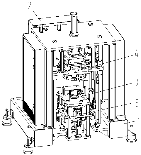
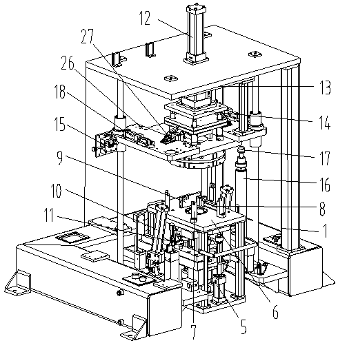
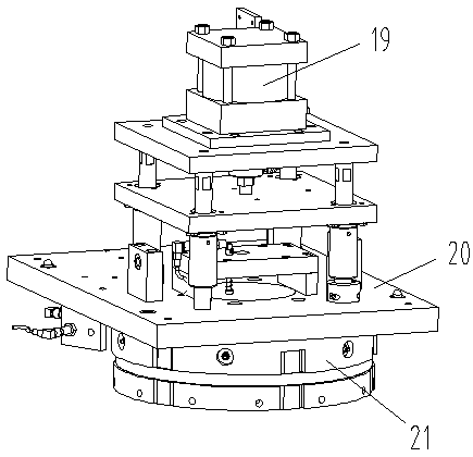
[0038] like Figure 1-Figure 8 As shown, the specific structure of the present invention is: a pinion part assembly mechanism that is convenient for short shaft press-in, which includes a frame 1 and a power distribution control box 2, and the frame 1 is provided with The locking carrier device 3, the upper part of the locking carrier device 3 is equipped with a gear socket mechanism 4, and the lower part is equipped with a short shaft insertion device 5. The frame 1 is provided with a center with a hole diameter larger than the tooth The carrier seat 6 of the hole of the shaft diameter, the described...


PUM


Abstract

The invention relates to a gear shaft part assembling mechanism convenient for the press-in of a short shaft. The gear shaft part assembling mechanism comprises a stander and a power distribution control box, wherein a locking carrier device matched with a gear shaft is arranged on the stander; the locking carrier device is matched with a gear sleeving mechanism on the upper side and a short shaftinserting device on the lower side; a carrier base is arranged on the stander, and a hole with the aperture larger than the diameter of the gear shaft is formed in the center of the carrier base; a fixed clamping block and a movable clamping block matched with each other are arranged on the carrier base, the movable clamping block is connected with a movable clamping cylinder on the carrier base,and the fixed clamping block and the movable clamping block are matched with a middle fixing block on the gear shaft; and the gear sleeving mechanism, a short shaft press-in mechanism and a movable clamping cylinder are connected to the power distribution control box. According to the gear shaft part assembling mechanism, an irregular middle fixing block is comprehensively clamped through the fixed clamping block and the movable clamping block, so that the deviation of the gear shaft in the assembling process is avoided, and meanwhile, the situation that a fixing part directly acts on the gear shaft is prevented, the damage of the gear shaft is avoided, and the assembly effect is improved.

Description

[0001] Original application number: 2017100019995 [0002] Date of original filing: January 3, 2017 [0003] Applicant of the original case: Dongguan Institute of Technology [0004] Title of the original application: an all-round locking assembly machine for gear shaft parts. technical field [0005] The invention relates to the field of gear shaft processing equipment, in particular to a gear shaft parts assembly mechanism that is convenient for short shaft press-in. Background technique [0006] The application of gear shaft parts is very extensive, and it is used in all walks of life. Most of them are as Figure 7 and Figure 8 As shown, it includes the fixedly connected pinion shaft 36 and the middle fixed block 37. The upper part of the pinion shaft needs to be inserted into the gear 38, and the lower part of the pinion shaft needs to be inserted into the short shaft with steps, and most of the steps are sequentially reduced from top to bottom. Little, there are the...

Claims


Application Information

Patent Timeline
Patent Type & Authority Applications(China)
IPC IPC(8): B23P19/027B25B11/02
CPCB23P19/027B23P21/002B25B11/02
Inventor 邓君徐红娇何楚亮
Owner 深圳市东钛宇精密机械有限公司
Learn More