
Thermistor feeding and forming apparatus

A thermistor and molding device technology, applied in resistors, resistor manufacturing, circuits, etc., can solve the problems of low production efficiency, high defective product rate, poor accuracy, etc., to improve production efficiency, reduce defective product rate, reduce The effect of production costs

Pending Publication Date: 2018-09-21
珠海凌智自动化科技有限公司
View PDF0 Cites 0 Cited by
  • Summary
  • Abstract
  • Description
  • Claims
  • Application Information

AI Technical Summary

Problems solved by technology

The existing molding method is completed manually with simple tooling, the production efficiency is low, and there will be problems such as high defective rate and poor precision in the manual completion process.

Method used


Image

  • Thermistor feeding and forming apparatus
  • Thermistor feeding and forming apparatus
  • Thermistor feeding and forming apparatus

Examples


Embodiment Construction

[0044] In order to make the objectives, technical solutions, and advantages of the embodiments of the present invention clearer, the technical solutions in the embodiments of the present invention will be described clearly and completely in conjunction with the accompanying drawings in the embodiments of the present invention. Obviously, the described embodiments It is a part of the embodiments of the present invention, not all the embodiments. Based on the embodiments of the present invention, all other embodiments obtained by those of ordinary skill in the art without creative work shall fall within the protection scope of the present invention.

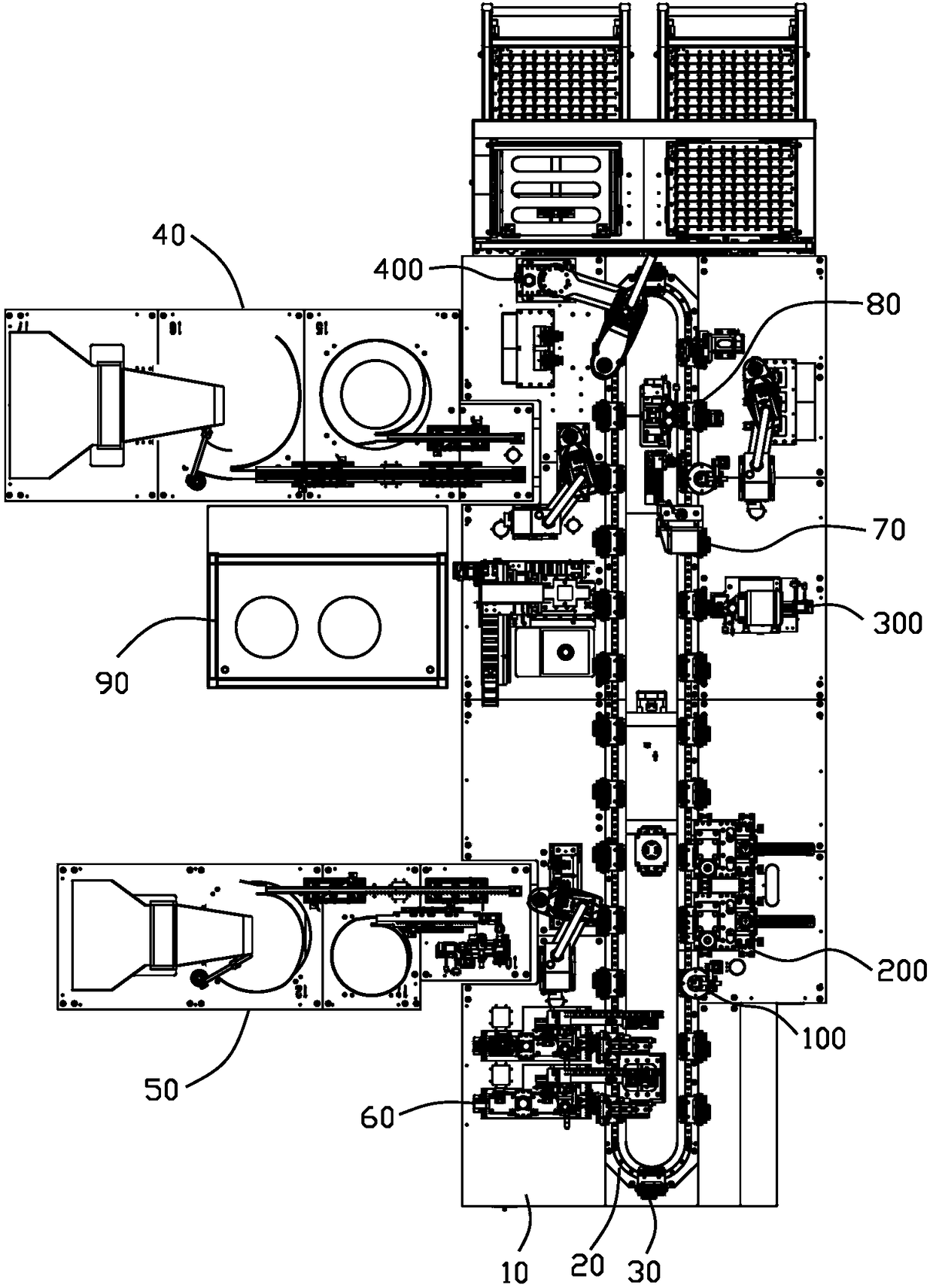
[0045] image 3 The top view of the automobile temperature sensor assembly line provided by the present invention, Figure 4 It is a schematic diagram of the three-dimensional structure of the automobile temperature sensor assembly line provided by the present invention. Such as image 3 with Figure 4 As shown, the automobile tempera...


PUM


Abstract

The invention provides a thermistor feeding and forming apparatus that is fully automated and that is used for improving forming efficiency and precision of thermistors. The thermistor feeding and forming apparatus (60) comprises mounting plate component (61), thermistor strip guide device (62), thermistor strip positioning device (63), thermistor strip pulling device (64), terminal deforming device (65), thermistor pickup device (66), and thermistor pin cutter (67). The thermistor feeding and forming apparatus according to the technical scheme provides full-automatic forming for thermistors,so that production efficiency is improved; defective rate is effectively decreased, and production cost is reduced accordingly.

Description

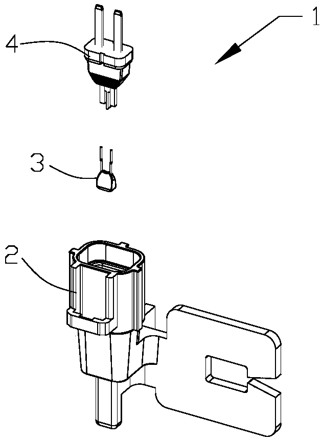
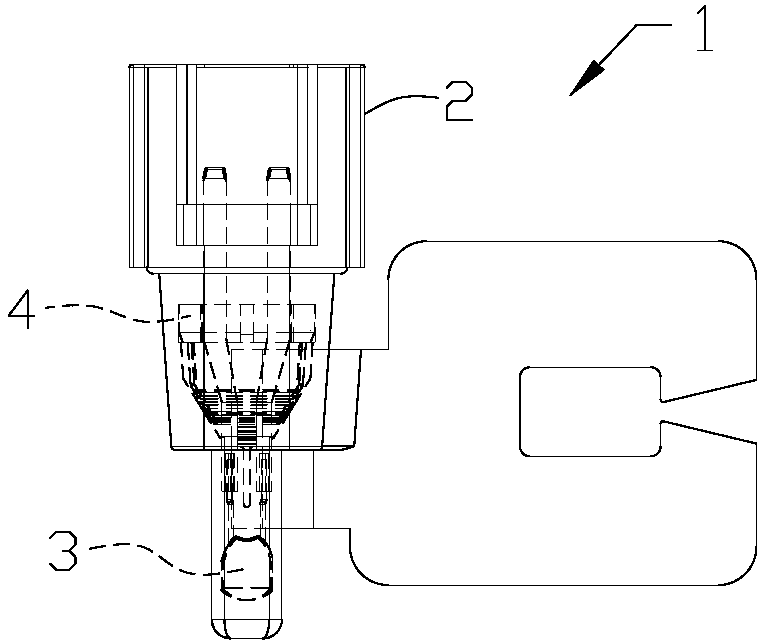
Technical field [0001] The invention relates to an automobile temperature sensor assembly line, in particular to a thermistor forming device used in the automobile temperature sensor assembly line. Background technique [0002] Automotive temperature sensors usually include three components: thermistor, base and terminal base. When assembling, the thermistor must be soldered to the terminal base, and then the base and terminal base must be assembled together. [0003] figure 1 Is a structural decomposition diagram of an existing automobile temperature sensor, figure 2 for figure 1 The three-dimensional schematic diagram of the assembled automobile temperature sensor in the figure, as shown in the figure, the automobile temperature sensor 1 includes: a base 2, a thermistor 3 and a terminal block 4; the thermistor 3 is soldered to the terminal block 4, and the terminal block 4 It is assembled and fixedly connected with the base 2. [0004] Thermistor incoming materials are usually in...

Claims


Application Information

Patent Timeline
Patent Type & Authority Applications(China)
IPC IPC(8): B23P21/00B23P23/06H01C17/00
CPCH01C17/00B23P21/00B23P23/06Y02P70/50
Inventor 不公告发明人
Owner 珠海凌智自动化科技有限公司
Learn More