Ceramic tile cutting machine
A cutting machine, ceramic tile technology, applied in the direction of stone processing tools, work accessories, manufacturing tools, etc., can solve the problems of slow cutting speed and insufficient cutting angle
- Summary
- Abstract
- Description
- Claims
- Application Information
AI Technical Summary
Problems solved by technology
Method used
Image

Examples
Embodiment 1
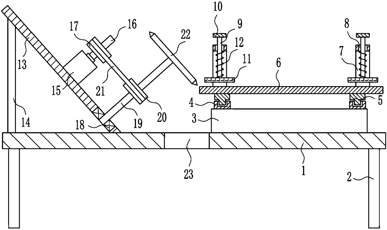
[0023] A cutting machine for tiles, such as Figure 1-3 As shown, it includes a bottom plate 1, a leg 2, a mounting seat 3, a slide rail 4, a slider 5, a placement plate 6, an n-shaped frame 7, a first guide rod 9, a handle 10, a rubber plate 11, and a first spring 12 , inclined plate 13, support plate 14, first motor 15, first rotating shaft 16, first pulley 17, first bearing block 18, second rotating shaft 19, second pulley 20, flat belt 21 and saw blade 22, base plate 1 Outriggers 2 are installed at the four corners of the bottom, mounting base 3 is installed on the top right of bottom plate 1, slide rails 4 are installed on the left and right sides of the top of mounting base 3, slide rails 4 are provided with sliders 5, and the top of slider 5 A placement plate 6 is installed, and an n-shaped frame 7 is installed on both sides of the top of the placement plate 6, and the n-shaped frame 7 is provided with a first guide hole 8, and the sliding type in the first guide hole 8...
Embodiment 2
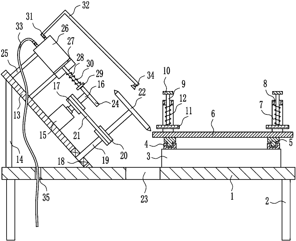
[0025] A cutting machine for tiles, such as Figure 1-3As shown, it includes a bottom plate 1, a leg 2, a mounting seat 3, a slide rail 4, a slider 5, a placement plate 6, an n-shaped frame 7, a first guide rod 9, a handle 10, a rubber plate 11, and a first spring 12 , inclined plate 13, support plate 14, first motor 15, first rotating shaft 16, first pulley 17, first bearing block 18, second rotating shaft 19, second pulley 20, flat belt 21 and saw blade 22, base plate 1 Outriggers 2 are installed at the four corners of the bottom, mounting base 3 is installed on the top right of bottom plate 1, slide rails 4 are installed on the left and right sides of the top of mounting base 3, slide rails 4 are provided with sliders 5, and the top of slider 5 A placement plate 6 is installed, and an n-shaped frame 7 is installed on both sides of the top of the placement plate 6, and the n-shaped frame 7 is provided with a first guide hole 8, and the sliding type in the first guide hole 8 ...
Embodiment 3
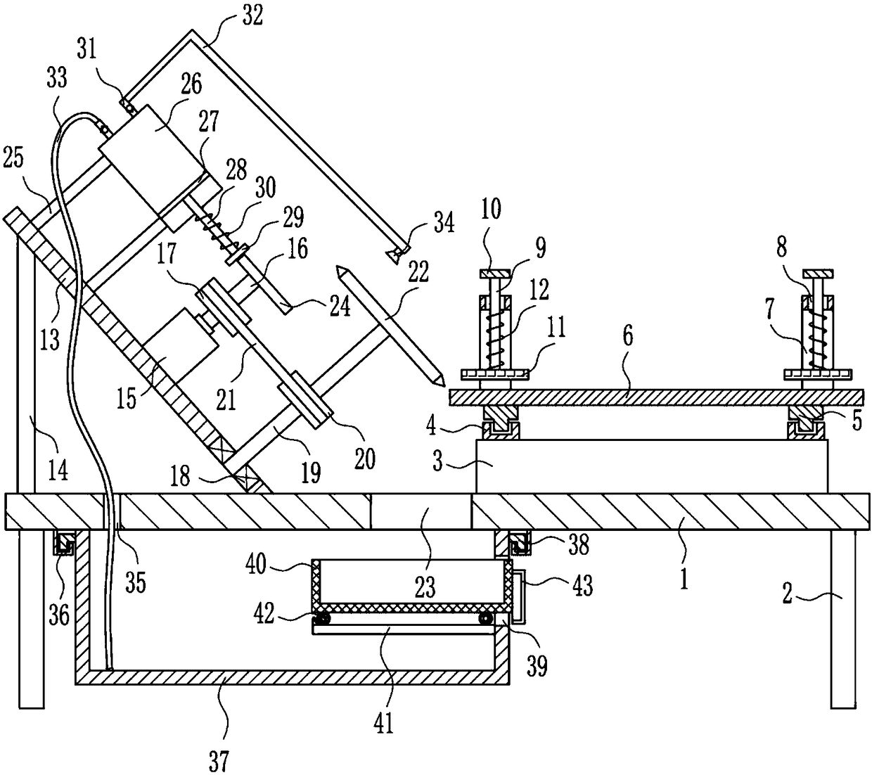
[0028] A cutting machine for tiles, such as Figure 1-3 As shown, it includes a bottom plate 1, a leg 2, a mounting seat 3, a slide rail 4, a slider 5, a placement plate 6, an n-shaped frame 7, a first guide rod 9, a handle 10, a rubber plate 11, and a first spring 12 , inclined plate 13, support plate 14, first motor 15, first rotating shaft 16, first pulley 17, first bearing block 18, second rotating shaft 19, second pulley 20, flat belt 21 and saw blade 22, base plate 1 Outriggers 2 are installed at the four corners of the bottom, mounting base 3 is installed on the top right of bottom plate 1, slide rails 4 are installed on the left and right sides of the top of mounting base 3, slide rails 4 are provided with sliders 5, and the top of slider 5 A placement plate 6 is installed, and an n-shaped frame 7 is installed on both sides of the top of the placement plate 6, and the n-shaped frame 7 is provided with a first guide hole 8, and the sliding type in the first guide hole 8...
PUM
 Abstract
Description
Claims
Application Information
 - R&D
- Intellectual Property
- Life Sciences
- Materials
- Tech Scout
- Unparalleled Data Quality
- Higher Quality Content
- 60% Fewer Hallucinations
Browse by: Latest US Patents, China's latest patents, Technical Efficacy Thesaurus, Application Domain, Technology Topic, Popular Technical Reports.
© 2025 PatSnap. All rights reserved.Legal|Privacy policy|Modern Slavery Act Transparency Statement|Sitemap|About US| Contact US: help@patsnap.com