Combined brake disc and braking device

A brake disc, combined technology, applied in the direction of brake disc, brake type, brake parts, etc., can solve the problem of disengagement, affecting the braking effect and service life of the brake disc, and the loose position of the friction disc and the brake disc base and other problems to achieve the effect of increasing the force bearing area, improving the braking effect and improving the service life

Pending Publication Date: 2018-09-21
BEIJING TIANYISHANGJIA NEW MATERIAL
View PDF1 Cites 2 Cited by
  • Summary
  • Abstract
  • Description
  • Claims
  • Application Information

AI Technical Summary

Problems solved by technology

[0005] Therefore, the technical problem to be solved by the present invention is that the friction disc body of the combined split brake disc in the prior art is easily affected by the braking friction force and the centrifugal force of the brake disc rotation during the vehicle braking process, making the friction disc relatively Due to the dual problems of horizontal displacement of the brake disc base and relative rotation along the circumferential direction of the brake disc base, the position between the friction disc and the brake disc base is loosened or even separated, which affects the braking effect and service life of the brake disc. The problem

Method used


Image

  • Combined brake disc and braking device
  • Combined brake disc and braking device
  • Combined brake disc and braking device

Examples


Embodiment 1

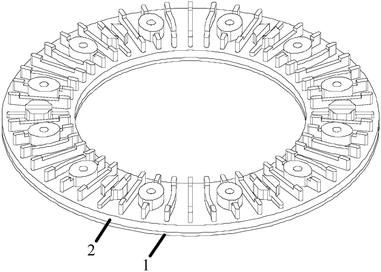
[0043] A brake device is described, which includes a combined brake disc with a wheel disc structure and a brake pad matched with the combined brake disc. Such as Figure 1 to Figure 4 The combined brake disc shown includes:

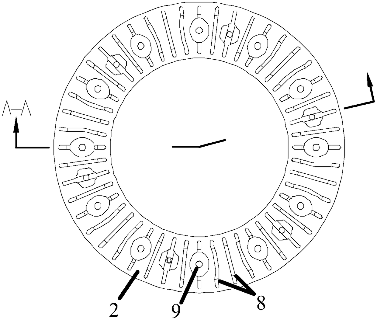
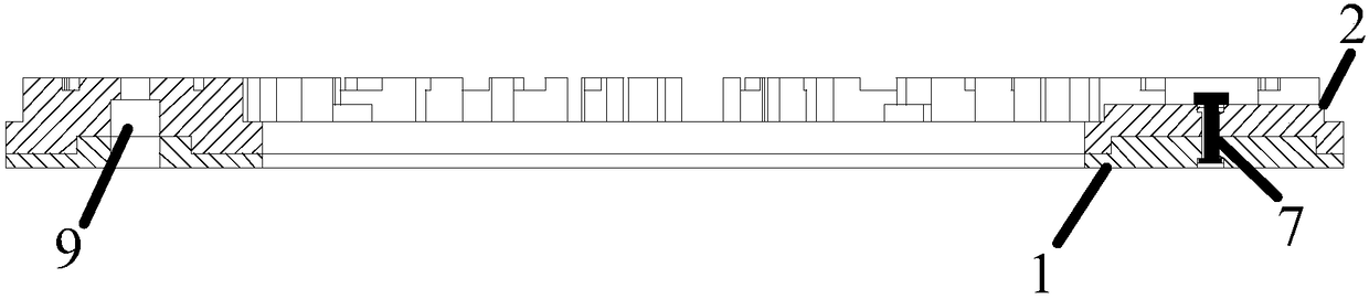
[0044] Such as Image 6 The brake disc base body 2 shown is an annular disc body. The upper surface of the brake disc base body 2 is provided with heat dissipation ribs, and the lower surface has an annular groove 4 arranged along the circumferential direction of the combined brake disc. The inner ring side wall of the annular groove 4 is arranged along the inner ring contour edge of the combined brake disc, and the outer ring side wall of the annular groove 4 is along the outer ring contour edge of the combined brake disc Set up

[0045] Such as Figure 5 The friction disc 1 shown is mounted on the lower surface of the brake disc base body 2. The upper surface of the friction disc 1 is provided with an annular boss 3 that is adapted to the annular groove 4...

Embodiment 2

[0050] The difference between this embodiment and the first embodiment is that the brake disc base 2 is an annular disc body, the upper surface of the brake disc base 2 is provided with heat dissipation ribs, and the lower surface has a circumferential direction of the combined brake disc. The ring boss 3;

[0051] The friction disc 1 is installed on the lower surface of the brake disc base body 2. The upper surface of the friction disc 1 is provided with an annular groove 4 that is adapted to the annular boss 3, and the annular groove 4 The inner ring side wall is arranged along the inner ring contour edge of the combined brake disc, and the outer ring side wall of the annular groove 4 is arranged along the outer ring contour edge of the combined brake disc; The groove 4 and the annular boss 3 are mated and clamped to prevent the friction disc from sliding in a relatively parallel position on the connecting surface with respect to the brake disc base body under the combined acti...

Embodiment 3

[0053] The difference between this embodiment and the first embodiment is that the protruding portion 5 and the inner concave portion 6 are concave-convex structures arranged on the connecting surface of the annular groove 4 and the annular boss 3. The protruding part 5 and the inner concave part 6 are strip-shaped structures arranged along the radial direction of the brake disc to prevent relative rotation of the friction disc.


PUM


Abstract

A combined brake disc comprises a brake disc base and friction discs, and the friction discs are mounted on one side or two sides of the brake disc base. A connection surface of the friction discs andthe brake disc base is provided with first limiting structures and second limiting structures; the first limiting structures are arranged peripherally along the combined brake disc to prevent relative parallel sliding, on the connection surface, of the friction discs relative to the brake disc base; the second limiting structures are arranged radially along the combined brake disc to prevent relative rotation, o the connection surface, of the friction discs relative to the brake disc base. By the first limiting structures and the second limiting structures, a stress surface of the brake discis improved, parallel sliding and peripheral sliding of the friction disc are effectively limited, and the problem of influences on braking effects and service life of the brake disc due to horizontaldisplacement of the friction discs relative to the brake disc base and relative rotation of the friction discs along the periphery of the brake disc base under braking friction and brake disc rotation action in a vehicle braking process in the prior art is solved.

Description

Technical field [0001] The invention relates to the technical field of brake discs, in particular to a combined brake disc and a braking device. Background technique [0002] The brake disc, also known as the brake disc, is an important component of the car body braking system. The brake disc rotates with the wheel or axle when the train or car is moving. When braking, the brake caliper clamps the brake disc, and the friction surface of the brake disc generates friction and absorbs kinetic energy, thereby decelerating and stopping the vehicle. . Therefore, the braking performance of the brake disc is directly related to the safety performance of the car body. [0003] In order to improve the braking performance of the brake disc, optimize the production cost and improve the competitiveness of the product, the prior art such as Chinese patent document CN207049233U, such as Figure 7 As shown, a high-speed train brake disc is disclosed. The brake disc includes a friction disc 101 an...

Claims


Application Information

Patent Timeline
Patent Type & Authority Applications(China)
IPC IPC(8): F16D65/12F16D65/84
CPCF16D65/123F16D65/127F16D65/128F16D2065/132F16D2065/1332F16D2065/1392
Inventor 吴佩芳释加才让崔新亮党一纵
Owner BEIJING TIANYISHANGJIA NEW MATERIAL
Why Eureka
Try Eureka