
Time characteristic measuring device and system

A time characteristic and measurement device technology, which is applied in the direction of measurement device, optical instrument test, optical performance test, etc., can solve the problems of inaccurate measurement of time characteristic and short pulse interval, etc.

Pending Publication Date: 2018-09-21
INST OF FLUID PHYSICS CHINA ACAD OF ENG PHYSICS
View PDF0 Cites 2 Cited by
  • Summary
  • Abstract
  • Description
  • Claims
  • Application Information

AI Technical Summary

Problems solved by technology

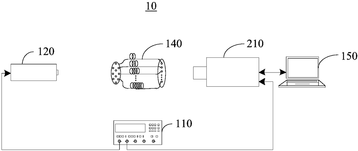
[0004] In order to overcome the above-mentioned deficiencies in the prior art, the purpose of the embodiment of the present invention is to provide a time characteristic measurement device and system, which can measure the time characteristics corresponding to different gears of the streak camera, especially for the gears of 10 ns and above Accurately measure the time characteristics of bits to avoid the situation that the time characteristics cannot be accurately measured due to too short pulse intervals when using the etalon calibration method

Method used


Image

  • Time characteristic measuring device and system
  • Time characteristic measuring device and system
  • Time characteristic measuring device and system

Examples


Embodiment Construction

[0034] The following will clearly and completely describe the technical solutions in the embodiments of the present invention with reference to the accompanying drawings in the embodiments of the present invention. Obviously, the described embodiments are only some, not all, embodiments of the present invention. The components of the embodiments of the invention generally described and illustrated in the figures herein may be arranged and designed in a variety of different configurations.

[0035] Accordingly, the following detailed description of the embodiments of the invention provided in the accompanying drawings is not intended to limit the scope of the claimed invention, but merely represents selected embodiments of the invention. Based on the embodiments of the present invention, all other embodiments obtained by those skilled in the art without making creative efforts belong to the protection scope of the present invention.

[0036] It should be noted that like numeral...


PUM


Abstract

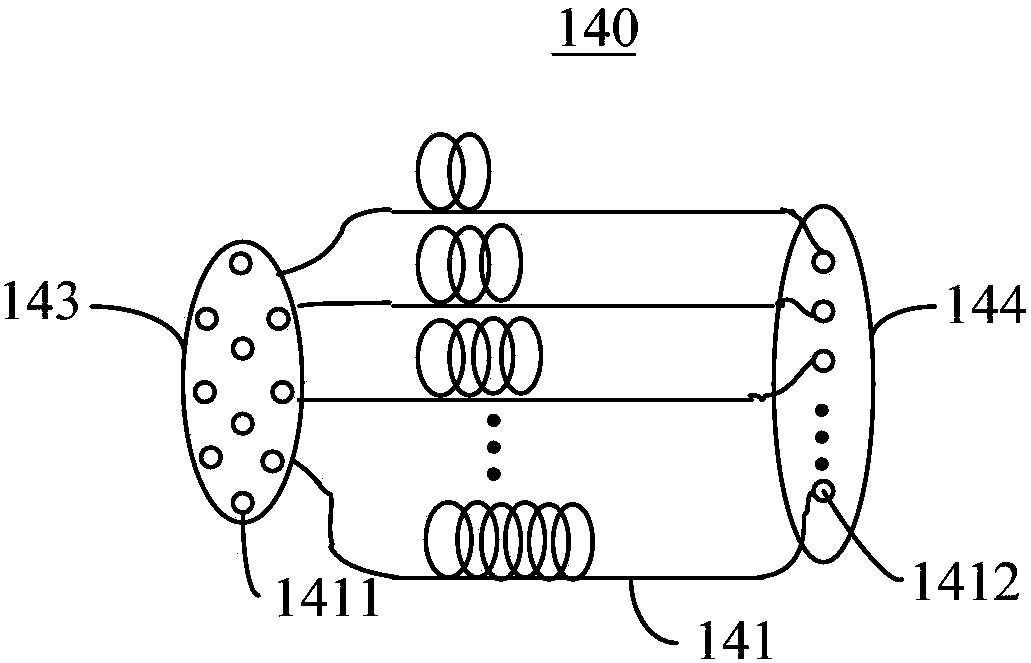
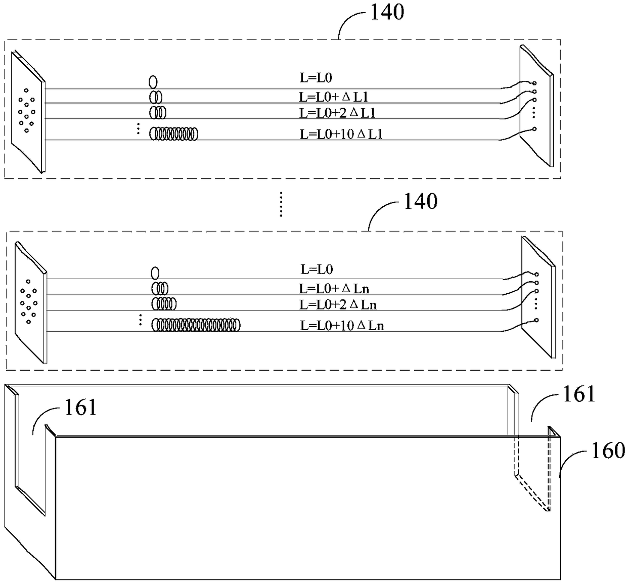
An embodiment of the invention provides a time characteristic measuring device and system. The device comprises a synchronous controller, a laser, an optical fiber array and a computing device. The synchronous controller is used for controlling working states of the laser and a streak camera through two paths of pulse signals. The laser is used for outputting pulse laser according to control of the synchronous controller. The optical fiber array comprises a plurality of fibers in different lengths. The optical fiber array is used for transmitting the pulse laser. The pulse laser output by thelaser irradiates to the streak camera through the optical fiber array. The streak camera is used for obtaining a scanned image, wherein the scanned image comprises laser points formed by the pulse laser. The computing device is used for calculating the time characteristic of the streak camera according to the distance between two laser points in the scanned image in the horizontal direction and the length difference between the corresponding two fibers. Therefore, the device and system can measure the time characteristic of the streak camera.

Description

technical field [0001] The invention relates to the technical field of high-speed photography, in particular to a time characteristic measuring device and system. Background technique [0002] Streak cameras, also known as variable image tube scanning cameras, are used to detect and record ultrafast phenomena. Streak cameras use slits to intercept one-dimensional line images on the target image, and continuously record their changes over time. Because of their ultra-high time resolution and the ability to continuously record events, they have become an important high-speed photography technology. Diagnostic equipment is widely used in research fields such as detonation physics, shock wave physics, accelerator physics, inertial confinement fusion (ICF) and laser-matter interaction. [0003] The temporal characteristic of the streak camera is an important indicator of the streak camera, which not only determines the accuracy of the experimental data in time, but also affects ...

Claims


Application Information

Patent Timeline
Patent Type & Authority Applications(China)
IPC IPC(8): G01M11/02
CPCG01M11/00
Inventor 何徽温伟峰冉茂杰赵新才刘宁文高鹏畅里华王旭
Owner INST OF FLUID PHYSICS CHINA ACAD OF ENG PHYSICS
Learn More