Dynamic wireless electric energy constant power output system and equivalent resistance control method thereof

A wireless energy and output system technology, applied in the direction of electrical components, circuit devices, etc., can solve the problems of large fluctuations in coupling coefficients and the inability to guarantee stable output of system power, and achieve constant system output power and reduce voltage and current stress. Effect

Active Publication Date: 2018-09-21
SOUTHWEST JIAOTONG UNIV
View PDF4 Cites 4 Cited by
  • Summary
  • Abstract
  • Description
  • Claims
  • Application Information

AI Technical Summary

Problems solved by technology

[0005] The purpose of the present invention is to solve the problem that in the field of rail transit, the existing dynamic wireless power transmission technology cannot guarantee the stable output of the system power due to the offset change of the spatial position and the large fluctuation of the coupling coefficient. Wireless energy dynamic constant power output system and its equivalent resistance control method

Method used


Image

  • Dynamic wireless electric energy constant power output system and equivalent resistance control method thereof
  • Dynamic wireless electric energy constant power output system and equivalent resistance control method thereof
  • Dynamic wireless electric energy constant power output system and equivalent resistance control method thereof

Examples


Embodiment 1

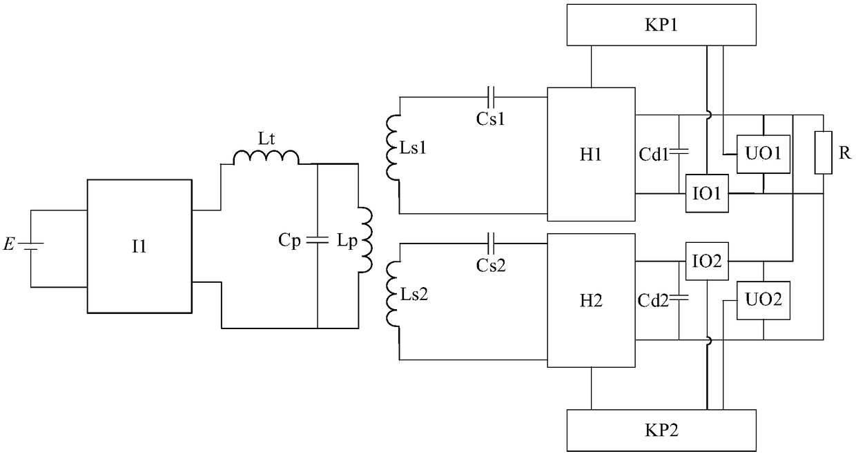
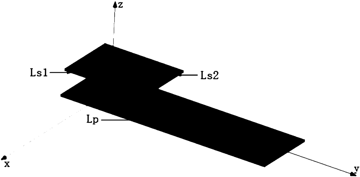
[0044] Such as figure 1 As shown, this embodiment provides a wireless energy dynamic constant power output system, including a sending end and a receiving end, the sending end includes a sending coil Lp, and the receiving end includes a secondary component 1 and a secondary component 2 respectively connected to the load R, The secondary side assembly 1 includes a receiving coil Ls1 parallel to the sending coil Lp, and the secondary side assembly 2 includes a receiving coil Ls2 parallel to the sending coil Lp, and the receiving coil Ls1 and the receiving coil Ls2 are respectively composed of square coils with a side length of L, The transmitting coil Lp is composed of four square coils with a side length L cascaded, the receiving coil Ls1 and the receiving coil Ls2 are overlapped to form a secondary coil group, and the length of the overlapping part of the receiving coil Ls1 and the receiving coil Ls2 is L / 2.

[0045] The sending end also includes a DC power supply E, a full-br...


PUM


Abstract

The invention discloses a dynamic wireless electric energy constant power output system and an equivalent resistance control method thereof and relates to the technical field of dynamic wireless electric energy transmission. The system comprises a transmitting end and a receiving end, wherein the transmitting end comprises a transmitting coil Lp; the receiving end comprises a secondary side assembly 1 and a secondary side assembly 2 which are connected with a load R; the secondary side assembly 1 comprises a receiving coil Ls1 parallel to the transmitting coil Lp; the secondary side assembly 2comprises a receiving coil Ls2 parallel to the transmitting coil Lp; the receiving coil Ls1 and the receiving coil Ls2 each comprise a square coil with a side length of L; the transmitting coil Lp comprises a plurality of square coils with the side length of L in cascade connection; the receiving coil Ls1 and the receiving coil Ls2 are overlapped to form a secondary side coil assembly, and the length of the overlapped part is L/2. According to the system disclosed by the invention, the total power is averagely distributed in the receiving end of the secondary side assembly 1 and the receivingend of the secondary side assembly 2 in a moving process, voltage-current stress of a switching tube can be decreased, and constant output power of the system is ensured.

Description

technical field [0001] The invention relates to the technical field of wireless energy dynamic transmission in rail transit, and more specifically relates to a wireless energy dynamic constant power output system and an equivalent resistance control method thereof. Background technique [0002] The wireless power transmission system uses the principle of high-frequency electromagnetic field near-field coupling, uses high-frequency magnetic field as the transmission medium, and realizes the wireless transmission of electric energy through the magnetic field coupling between the sending coil and the receiving coil. The wireless power transmission system is mainly composed of two parts, one is the transmitting end connected to the power supply side, and the other is the receiving end located on the load side. The energy is transmitted from the transmitting end to the receiving end through electromagnetic induction. The existing wireless power transmission system is mainly compo...

Claims


Application Information

Patent Timeline
Patent Type & Authority Applications(China)
IPC IPC(8): H02J50/10H02J50/12
CPCH02J50/10H02J50/12
Inventor 麦瑞坤刘登伟刘野然何正友
Owner SOUTHWEST JIAOTONG UNIV
Why Eureka
Try Eureka