Rotor structure, permanent magnet auxiliary synchronous reluctance motor and electric vehicle

A technology of rotor structure and rotor body, which is applied to electric vehicles, synchronous motors with stationary armatures and rotating magnets, motors, etc., can solve the problem of low motor power, and achieve the goal of increasing output power, increasing power, and optimizing direction Effect

Active Publication Date: 2018-09-21
ZHUHAI GREE REFRIGERATION TECH CENT OF ENERGY SAVING & ENVIRONMENTAL PROTECTION
View PDF7 Cites 8 Cited by
  • Summary
  • Abstract
  • Description
  • Claims
  • Application Information

AI Technical Summary

Problems solved by technology

[0003] The main purpose of the present invention is to provide a rotor structure, permanent magnet assisted synchronous reluctance motor and electric vehicle, to solve the problem of low motor power in the prior art

Method used


Image

  • Rotor structure, permanent magnet auxiliary synchronous reluctance motor and electric vehicle
  • Rotor structure, permanent magnet auxiliary synchronous reluctance motor and electric vehicle
  • Rotor structure, permanent magnet auxiliary synchronous reluctance motor and electric vehicle

Examples


Embodiment Construction

[0030] It should be noted that, in the case of no conflict, the embodiments in the present application and the features in the embodiments can be combined with each other. The present invention will be described in detail below with reference to the accompanying drawings and examples.

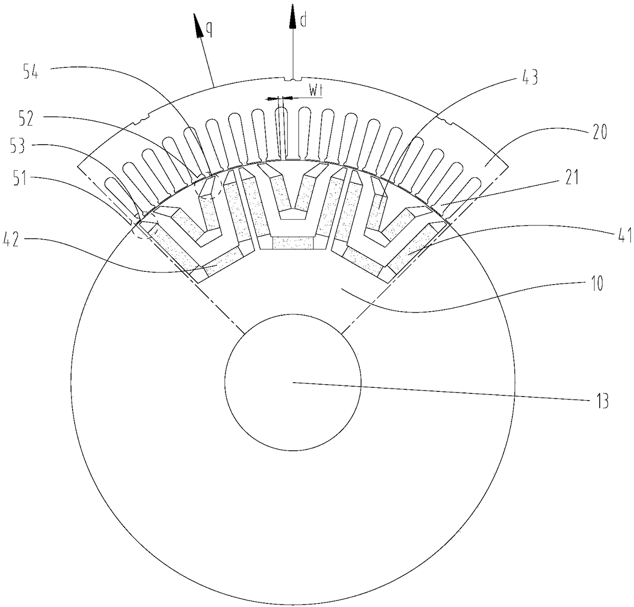
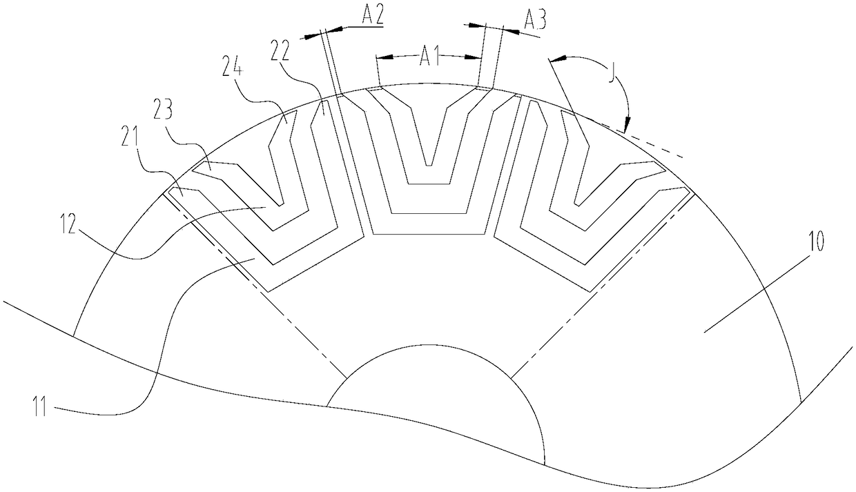
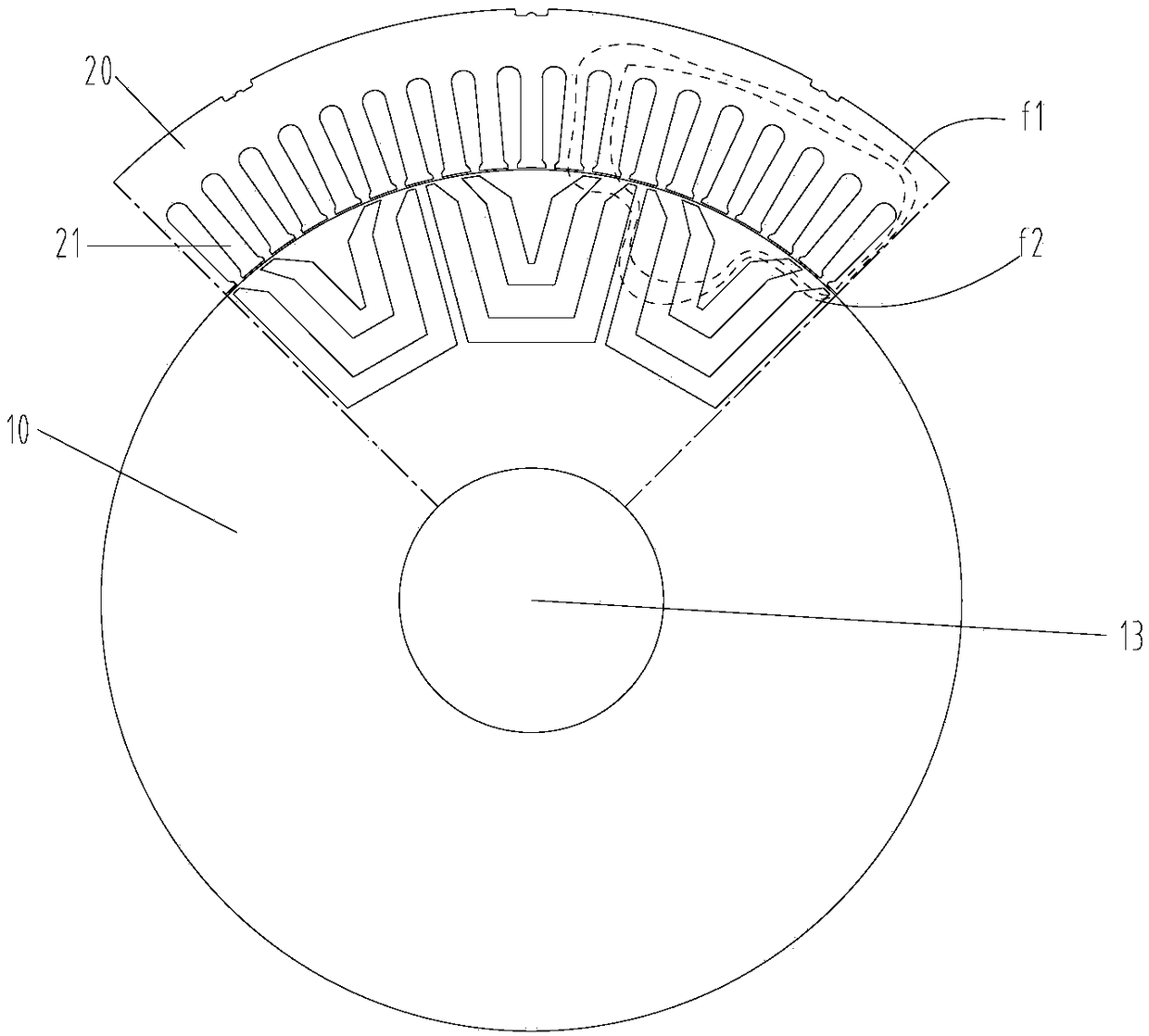
[0031] to combine Figure 1 to Figure 4 As shown, according to an embodiment of the present invention, a rotor structure is provided.

[0032] Specifically, the rotor structure includes a rotor body 10, which is provided with a permanent magnet slot group, and the permanent magnet slot group includes an outer permanent magnet slot 12, and the rotor body 10 is also provided with a third folding groove 23 and a fourth folding groove. Slot 24. Wherein, the third folded groove 23 communicates with the first end of the outer layer permanent magnet groove 12, the fourth folded groove 24 communicates with the second end of the outer layer permanent magnet groove 12, the geometry of the length direct...


PUM


Abstract

The present invention provides a rotor structure, a permanent magnet auxiliary synchronous reluctance motor and an electric vehicle. The rotor structure comprises a rotor body, the rotor body is provided with a permanent magnet slot group, the permanent magnet slot group comprises an outer layer of permanent magnet slot, and the rotor body is provided with a third folding slot and a fourth foldingslot. A third inclination angle is formed by a geometric center line of the third folding slot in the length direction and a geometric center line of the first end of the outer layer of permanent magnet slot in the length direction, and a fourth inclination angle is formed by a geometric center line of the fourth folding slot in the length direction and a geometric center line of the second end of the outer layer of permanent magnet slot in the length direction; the extension cord of the side wall of the third folding slot and the outer edge of the rotor body are intersected to a first point,the extension cord of the side wall of the fourth folding slot and the outer edge of the rotor body are intersected to a second point, the radian of the connection line of the first point and the second point is A1, wherein A1>0.63*360 degrees/p. Through the relation of the angles between the folding slots and the number P of poles of the rotor structure, the trend of the magnetic line of force is optimized, and the output power of the permanent-magnet torque is improved.

Description

technical field [0001] The invention relates to the technical field of motor equipment, in particular to a rotor structure, a permanent magnet assisted synchronous reluctance motor and an electric vehicle. Background technique [0002] The torque component of the permanent magnet synchronous reluctance motor includes permanent magnet torque and reluctance torque. Affected by the reluctance torque component, the rotor structure has a great influence on the torque ripple. Therefore, the optimization of torque ripple has always been one of the research and development priorities of this motor. The torque ripple level of existing permanent magnet reluctance motors is still low, which affects the power of the motor. Contents of the invention [0003] The main purpose of the present invention is to provide a rotor structure, a permanent magnet assisted synchronous reluctance motor and an electric vehicle, so as to solve the problem of low motor power in the prior art. [0004]...

Claims


Application Information

Patent Timeline
Patent Type & Authority Applications(China)
IPC IPC(8): H02K1/27H02K29/03
CPCH02K1/2766H02K29/03H02K2213/03Y02T10/64H02K1/2773H02K21/14B60K1/00
Inventor 黄辉胡余生陈彬童童肖勇卢素华
Owner ZHUHAI GREE REFRIGERATION TECH CENT OF ENERGY SAVING & ENVIRONMENTAL PROTECTION
Why Eureka
Try Eureka