Waste debris collection device for gear processing

A collection device and gear technology, applied in metal processing equipment, metal processing machine parts, grinding/polishing safety devices, etc., can solve the problems of unclean waste cleaning and device stuck

Active Publication Date: 2018-09-25
重庆博创知识产权运营有限公司
View PDF3 Cites 9 Cited by
  • Summary
  • Abstract
  • Description
  • Claims
  • Application Information

AI Technical Summary

Problems solved by technology

[0005] The purpose of the present invention is to solve the problem that the waste chip

Method used


Image

  • Waste debris collection device for gear processing
  • Waste debris collection device for gear processing
  • Waste debris collection device for gear processing

Examples


Embodiment Construction

[0027] The following is further described in detail through specific implementation methods:

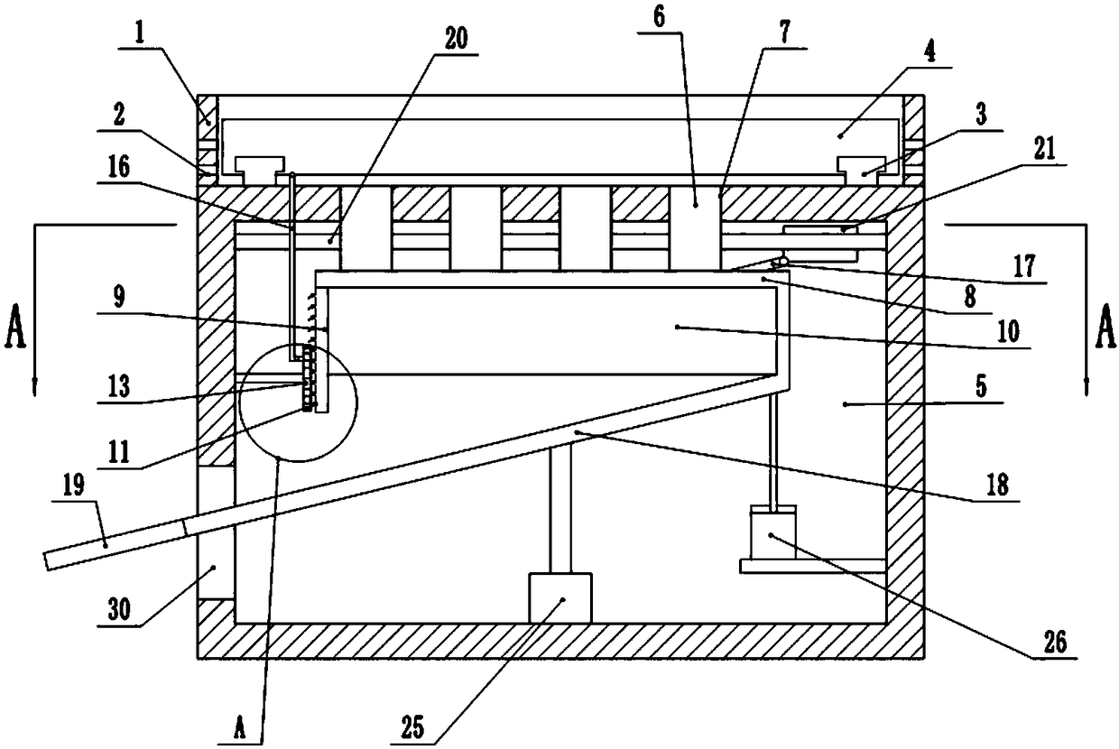
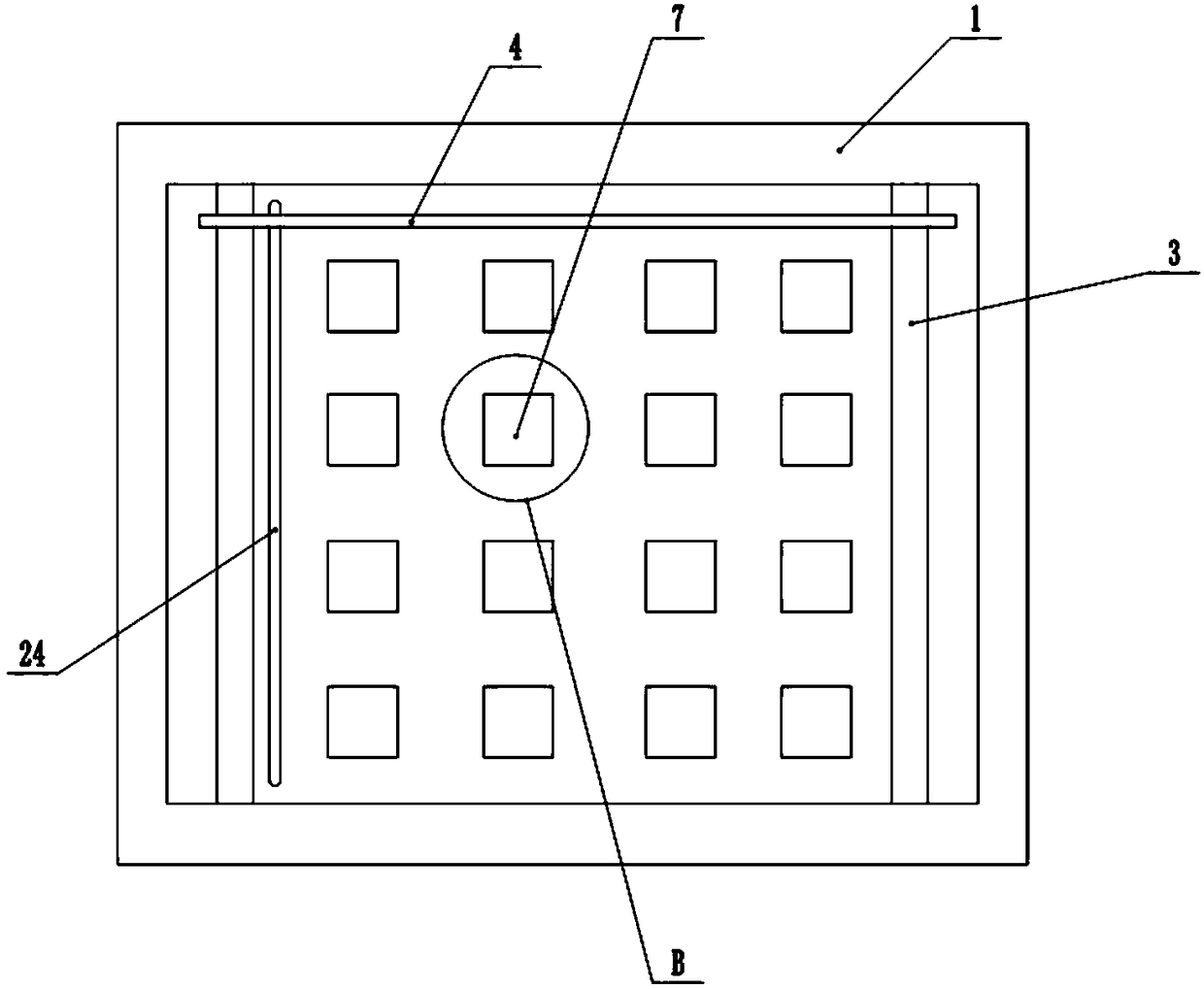
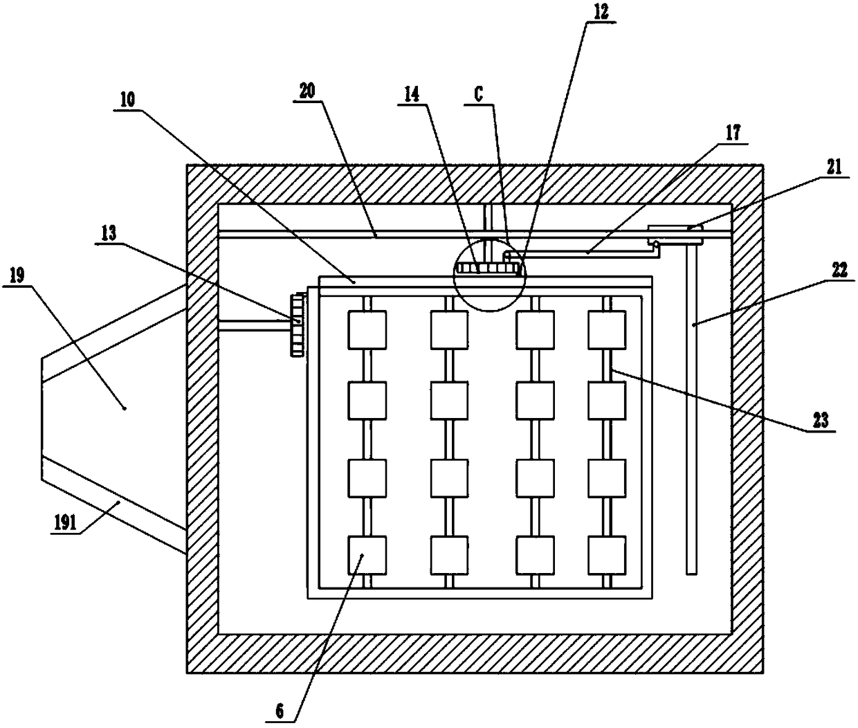
[0028] The reference signs in the drawings of the description include: collection table 1, filter hole 2, slide rail 3, scraper 4, collection chamber 5, boss 6, chip removal hole 7, support frame 8, first vertical plate 9, second Two vertical plates 10, first set of teeth 11, second set of teeth 12, first gear 13, second gear 14, straight plate 15, first connecting rod 16, second connecting rod 17, inclined plate 18, chip removal plate 19 , slide bar 20, slide block 21, brush plate 22, support bar 23, through groove 24, cylinder 25, piston cylinder 26, rubber rod 27, exhaust hole 28, air inlet hole 29, outlet hole 30, baffle plate 191.

[0029] The embodiment is basically as attached figure 1 Shown: a waste collection device for gear processing, including a collection table 1; The left and right ends of the upper surface are facing with a slide rail 3, the slide rail 3 is slidably ...


PUM


Abstract

The invention belongs to the technical field of gear processing, and particularly discloses a waste debris collection device for gear processing. The device comprises a collecting table; an electromagnet is arranged on the upper surface of the collecting table; filtering holes and sliding rails are disposed in the upper surface of the collecting table; a scraper blade is connected with the slidingrails in a sliding manner; an air cylinder is arranged at a bottom end of the collecting table; an inclined plate is connected with a piston rod of the air cylinder; a support frame is arranged abovethe inclined plate; support strips with bosses are arranged in the support frame; chip removing holes are arranged in the collecting table; the chip removing holes are rotationally connected with rubber rods; a sliding rod is arranged on the support frame; a sliding block is connected with the sliding rod in a sliding manner; two vertical plates are arranged on the support frame; the first vertical plate is hinged with a first group of teeth with end portions bent downwardly; the second vertical plate is hinged with a second group of teeth with the end portions bent upwardly; two gears respectively meshed with the two group of teeth are arranged in a collecting chamber; the first gear is hinged with the scraper blade through one connecting rod; and the second gear is hinged with the sliding block through the other connecting rod. The invention aims at solving the problem that the waste debris collection device for gear processing is deadlocked easily because the waste debris is not cleaned up properly.

Description

technical field [0001] The invention belongs to the technical field of gear processing, and specifically discloses a waste collection device for gear processing. Background technique [0002] A gear is a mechanical element with teeth on the rim that can continuously cohere to transmit motion and power. It is a toothed mechanical part that can gnaw on each other. The diameter of the large gear is twice the diameter of the small gear. The application of gears in transmission has appeared very early. The production and processing of gears is an important part of industrial production. During the process of gear processing, a large amount of metal waste is often produced, and the on-site workers are usually left alone. Scatter, or wear protective gloves, wipe it on the ground with a tablecloth, and clean it up after a period of time. However, waste debris usually also has many burrs, and most of them are sharp and irregular shapes. When they are scattered on the workbench or th...

Claims


Application Information

Patent Timeline
IPC IPC(8): B23Q11/00B24B55/06
CPCB23Q11/0064B24B55/06
Inventor 曾义杰
Owner 重庆博创知识产权运营有限公司
Why Eureka
Try Eureka