Impeller for centrifugal pump

A technology for centrifugal pumps and impellers, which is applied to parts, pumps, and pump elements of pumping devices for elastic fluids, and can solve the problems of impellers being easily worn and stuck and manufacturing costs, and reduce processing difficulty and cost. , Guarantee wear resistance and reduce the effect of axial dimension

Active Publication Date: 2011-07-06
新界泵业(浙江)有限公司
View PDF6 Cites 6 Cited by
  • Summary
  • Abstract
  • Description
  • Claims
  • Application Information

AI Technical Summary

Problems solved by technology

[0004] The technical problem to be solved and the technical task proposed by the present invention are to overcome the defects that the existing impeller is easy to be worn and stuck and the manufacturing cost is high, and to provide an impeller for a centrifugal pump

Method used


Image

  • Impeller for centrifugal pump
  • Impeller for centrifugal pump
  • Impeller for centrifugal pump

Examples


Embodiment Construction

[0032] The present invention will be further described below in conjunction with the accompanying drawings of the description.

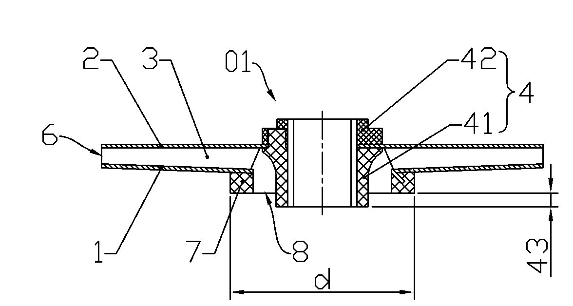
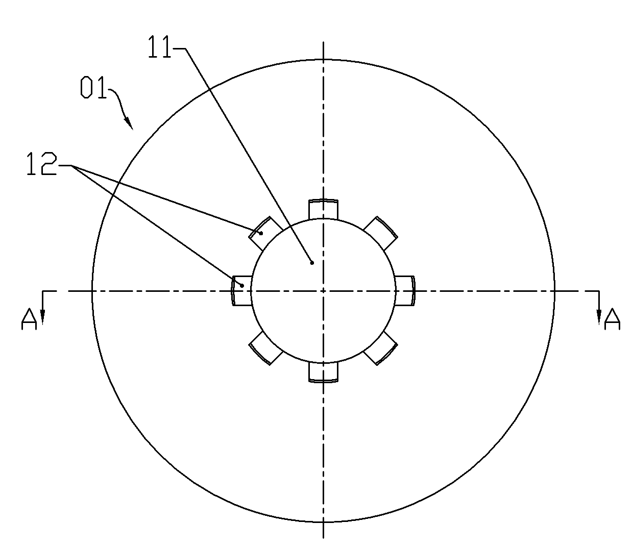
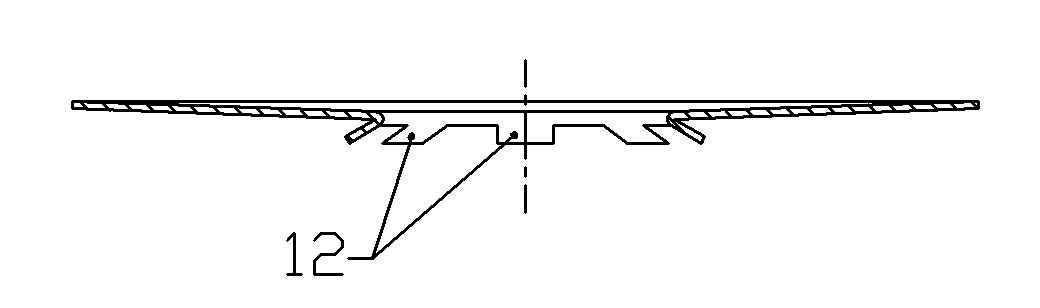
[0033] The impeller 01 for the centrifugal pump of the present invention, such as figure 1 As shown, it includes a front cover 1, a rear cover 2, a plurality of blades 3, and a hub 4. The front cover 1 and the rear cover 2 are circular and have through holes 11, 21 at the centers of the two, and the blades 3 It is in the shape of a curved plate, the front cover 1, the rear cover 2, and the blades 3 are made of stainless steel and the blades are distributed radially (see Figure 12 ) between the front cover 1 and the rear cover 2, the edge of the blade 3 is welded (such as by butt welding) with the front cover 1 and the rear cover 2, and the centrifugal channel 5 is formed between adjacent blades and The outer end of the centrifugal passage forms the impeller outlet 6, and the edge of the through hole 11 of the front cover plate 1 is shaped on a plas...


PUM


Abstract

The invention discloses an impeller for a centrifugal pump. The traditional impeller is easy to wear and lock and has high manufacturing cost. In the impeller for the centrifugal pump, a front cover plate, a rear cover plate and blades are made of stainless steel materials, the plurality of blades are radially arranged between the front cover plate and the rear cover plate, the blades, the front cover plate and the rear cover plate are welded, the edge of a through hole of the front cover plate is provided with a plastic opening ring, the external diameter of the plastic opening ring is larger than the inner diameter of a center hole of a guide blade cover plate, a hub is made of plastics and assembled on the rear cover plate, the front end of the hub extends into the plastic opening ring, a radial clearance is kept between the front end of the hub and the plastic opening ring to form an impeller inlet, and a structure which can move along a pump shaft is adopted in an inner hole of the hub. When the pump is assembled, the front end surface of the plastic opening ring contacts the guide blade cover plate, the impeller can float on the pump shaft through the hub to automatically regulate the size of an axial clearance, thereby the problems of impeller wear and locking caused by silt can be solved to a certain extent. Moreover, by adopting the impeller with the assembly structure, the processing difficulty and the construction cost are reduced.

Description

technical field [0001] The invention relates to a centrifugal impeller, in particular to an impeller for a centrifugal pump in which the mouth ring and the wheel hub are made of plastic and are clearance-fitted with the pump shaft so as to be able to float freely during use. Background technique [0002] The centrifugal impellers currently on the market are mostly made of stainless steel, and their mouth rings are all cylindrical stainless steel rings with the front cover turned outward, and the stainless steel impellers on the market are all axially positioned on the pump shaft (such as through It is realized by assembling a shaft sleeve on the pump shaft), the mouth ring and the guide vane cover plate have overlapping parts in the axial direction, in order to avoid leakage, the radial gap between the overlapping parts should be small to form a seal, and the overlapping parts The radial clearance remains unchanged during work, but when the silt content in the medium is larg...

Claims


Application Information

Patent Timeline
Patent Type & Authority Applications(China)
IPC IPC(8): F04D29/22
Inventor 陈华青
Owner 新界泵业(浙江)有限公司
Why Eureka
Try Eureka