
Gripper and cross-member having at least one gripper

A technology for grabbers and hanging beams, applied in the field of grabbers and hanging beams with at least one grabber, can solve problems such as heavy load damage, reduce space volume, reduce damage potential, reduce The effect of small shipping costs

Active Publication Date: 2018-09-25
GKS STAHL & MASCHENBAU
View PDF11 Cites 0 Cited by
  • Summary
  • Abstract
  • Description
  • Claims
  • Application Information

AI Technical Summary

Problems solved by technology

Furthermore, the problem with conventional rigid C-grippers or C-shaped elements is that the greatest loads and thus the highest damage potential occur in the corner regions of the vertical supports (also referred to as the back )middle

Method used


Image

  • Gripper and cross-member having at least one gripper
  • Gripper and cross-member having at least one gripper
  • Gripper and cross-member having at least one gripper

Examples


Embodiment Construction

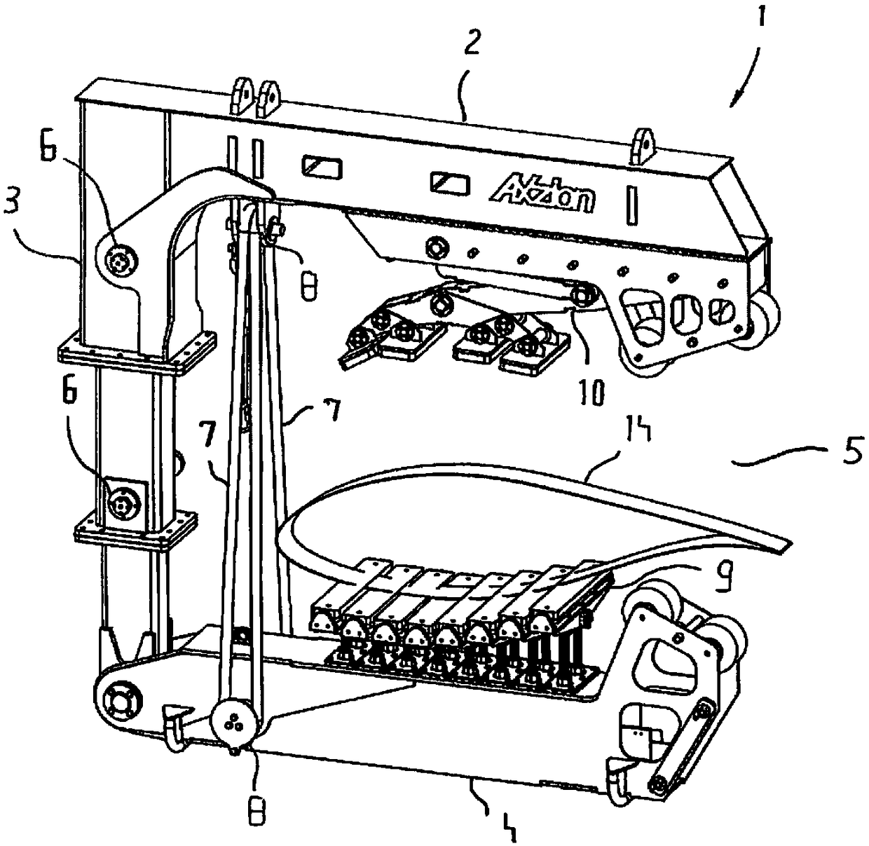
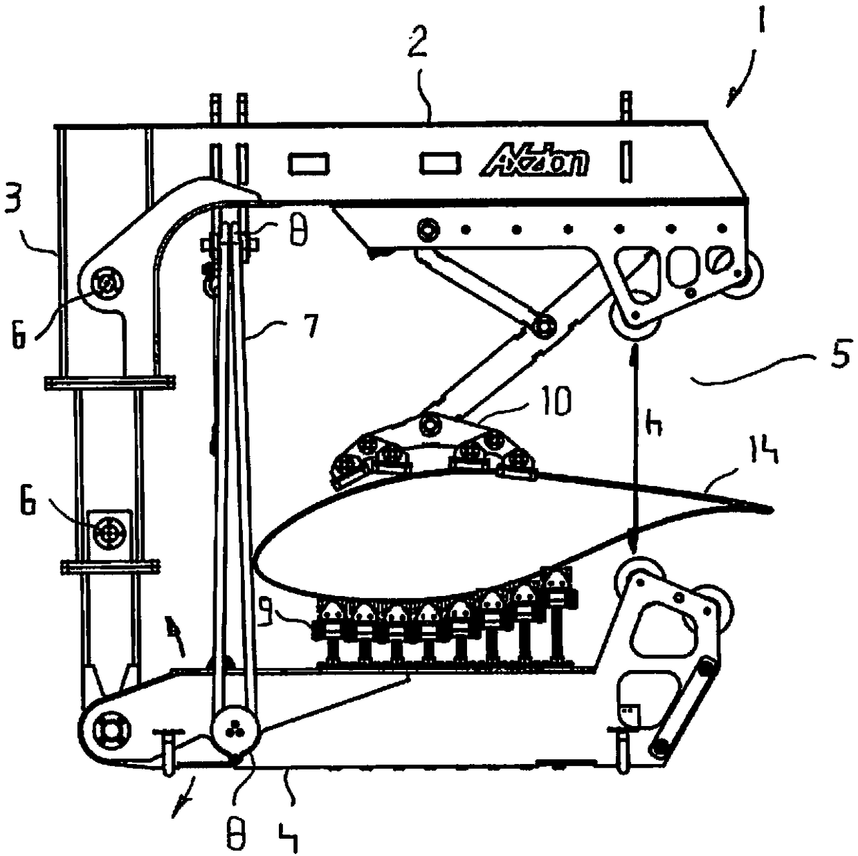
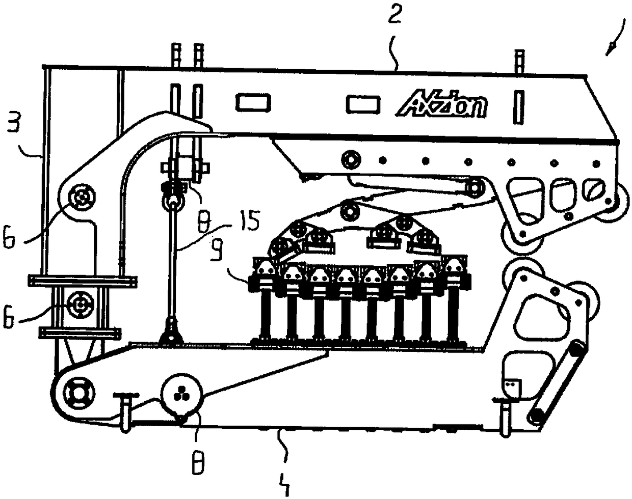
[0025] exist figure 1 The C-shaped gripper 1 is seen in the figure, which can be arranged at the suspension beam 11. The C-grabber 1 consists of an upper support 2 , a vertical support 3 and a brace support 4 . The cradle support 4 has a plurality of cradle sections 9 and forms a so-called hook base onto which a lifting load 14 can be placed. The upper support 2 and the vertical support 3 are rigidly connected to each other as in conventional design structures and are arranged at right angles to each other. The support support 4 is not rigidly connected to the vertical support 3 in a rotatably supported manner, to be more precise in such a way that the opening of the C-shaped gripper 1 has a clean Dimension (h) can be changed, for example can be enlarged or reduced. The brace support 4 is thus pivotable, which in figure 2 identified by arrows. Furthermore, the vertical support 3 is telescopic, in the embodiment double telescopic.

[0026] The locking of the telescoping ...


PUM


Abstract

The present invention relates to a gripper and a cross-member having at least one gripper, and particularly relates to a C-gripper for arranging at a cross-member or at a suspension element and a cross-member having at least one such C-gripper for transporting loads, wherein the height of the C-gripper is adjustable.

Description

technical field [0001] The invention relates to a C-shaped gripper for arrangement on a lifting beam or a carrier and a lifting beam for transporting lifting goods with at least one such C-shaped gripper, wherein the C-shaped gripper is at its height can be adjusted. Background technique [0002] C-shaped grippers have been known for many years, for example from EP 2873641 A1 in particular. The C-gripper disclosed there is a C-gripper with a rigid structure. This previously resulted in disadvantages when transporting. That is to say, such a grabber cannot usually be loaded into a common cargo box, because it is precisely in the case of use on board, for example, in the case of assembling an offshore wind power installation, when there is to be used Such a gripper or a lifting beam having at least one such gripper is advantageous. Furthermore, the problem with conventional rigid C-grippers or C-shaped elements is that the greatest loads and thus the highest damage potenti...

Claims


Application Information

Patent Timeline
Patent Type & Authority Applications(China)
IPC IPC(8): B66C1/28B66C1/44
CPCB66C1/108B66C1/28B66C1/44B66C1/24B66C1/445
Inventor 博里斯·弗兰克
Owner GKS STAHL & MASCHENBAU
Learn More