In-well magnetic chipping fisher

An overshot and magnetic technology, applied in wellbore/well parts, earthwork drilling and mining, etc., can solve problems such as low construction efficiency and achieve the effect of improving construction efficiency

Active Publication Date: 2018-09-25
CHINA PETROLEUM & CHEM CORP +1
3 Cites 0 Cited by

AI-Extracted Technical Summary

Problems solved by technology

However, the fishing tools in the prior art can only be used to fish debris and cannot b...

Method used

Salvage main body 1 comprises magnetic steel 7 and the conversion joint 8 that is installed on the downstream end of magnetic steel, electric control tool 10 links to each other with conversion joint 8, and cable 3 then passes through magnetic steel 7 and conversion joint 8 and is also connected with electric Control tool 10 is conn...

Abstract

The invention relates to an in-well magnetic chipping fisher. The in-well magnetic chipping fisher comprises a magnetic fishing main body for fishing chippings and an electrically controlled tool connected with the downstream end of the fishing main body, wherein a cable axially penetrating through the fishing main body and connected with the electrically controlled tool. The in-well magnetic chipping fisher comprises the magnetic fishing main body and the electrically controlled tool, thus operation of the electrically controlled tool is achieved while chipping fishing, and the construction efficiency is improved.

Application Domain

Borehole/well accessories

Technology Topic

Electrical and Electronics engineering

Image

  • In-well magnetic chipping fisher
  • In-well magnetic chipping fisher
  • In-well magnetic chipping fisher

Examples

  • Experimental program(1)

Example Embodiment

[0021] The present invention will be further described below in conjunction with the drawings.
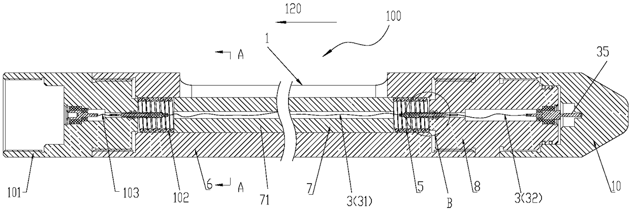
[0022] In this application document, the direction term "upstream" is as figure 1 As shown by the arrow 120, "downstream" is the opposite direction to "upstream".
[0023] figure 1 The structure of the in-well debris magnetic fishing device 100 (hereinafter referred to as the fishing device 100 for short) according to the present invention is schematically shown. Such as figure 1 As shown, the salvage device 100 includes a salvage body 1, an electric control tool 10 connected to the downstream end of the salvage body 1, and a cable 3. The salvage body 1 has magnetism to absorb metal debris in the well and complete the salvage operation. The cable 3 axially penetrates the salvage main body 1 and is connected to the electric control tool 10 to supply power and/or transmit signals to the electric control tool 10. In this way, when the salvage device 100 is used to carry out debris fishing operations in the well, the electronic control tool 10 can operate independently, thereby realizing the simultaneous operation of the electronic control tool 10 and the debris fishing operation. In one embodiment, the electric control tool 10 may be a cable perforation tool and/or an autopsy test tool, which are well known to those skilled in the art, and will not be repeated here.
[0024] The salvage body 1 includes a magnet 7 and a conversion joint 8 installed at the downstream end of the magnet. The electric control tool 10 is connected to the conversion joint 8, and the cable 3 passes through the magnet 7 and the conversion joint 8 and is also connected to the electric control tool 10. Connected. The magnet 7 is used to absorb debris in the well. By using the adapter 8, various types of electrician tools 10 can be conveniently used for the overshot 100. In addition, the conversion joint 8 separates the magnetic steel 7 and the electrical tool 10 to avoid interference between the two during work.
[0025] Preferably, the cable 3 is composed of multiple sections in the magnetic steel 7 and the conversion joint 8 respectively. Such as figure 1 with 3 , The cable 3 includes a first section 31 in the magnetic steel 7 and a second section 32 in the conversion joint 8. The first section 31 and the second section 32 are detachably connected. For example, the downstream end of the first section 31 is connected with a socket 33, and the upstream end of the second section 32 is connected with a first plug 34 matching the socket 33. In addition, a second plug 35 is connected to the downstream end of the second section 32, and the electric control tool 10 is plug-connected to the second plug 35. When assembling the magnetic steel 7, the adapter 8 and the electric control tool 10, it is convenient to plug the cables 3 together, and plug the cable 3 and the electric control tool 10 together, thereby forming a passage. This greatly simplifies the assembly process of the overshot 100.
[0026] Such as figure 2 As shown, the magnetic steel 7 includes a magnetic steel column 71 and a plurality of magnetic fishing wings 6 extending radially outward from the magnetic steel column 71. The cable 3 penetrates the magnetic steel column 71. Preferably, these fishing wings 6 are strips extending axially. In this case, the adapter 8 is connected to these fishing wings 6. These fishing wings 6 are spaced apart in the circumferential direction, so that a recess 72 is formed between adjacent fishing wings 6. In the process of salvaging the debris, a large amount of debris is absorbed in the recess 72. Therefore, when the overshot 100 is lifted out of the well, possible obstacles will not scratch the debris in the recess 72, so that the fishing efficiency of the debris can be greatly improved.
[0027] Still like figure 1 As shown, an elastic member 5 is provided between the conversion joint 8 and the magnetic steel column 71. In one embodiment, the elastic member 5 is a spring. When the overshot 100 is lowered into the well, the elastic member 5 will buffer the external impact of the magnetic steel column 71 and play a role of protecting the magnetic steel column 71.
[0028] Preferably, an elastic member 102 is also provided between the upstream end of the magnetic steel column 71 and the upper joint 101. In one embodiment, the elastic member 102 is a spring. During the lifting of the overshot 100, the elastic member 102 will buffer the external impact of the magnetic steel column 71, and play a role of protecting the magnetic steel column 71. It should also be noted that in this case, the cable 3 also penetrates the upper joint 101. For example, the cable section 103 of the cable 3 may be provided in the upper joint 101, and the cable section 103 and the first section 31 are connected together by plug-socket plug-in connection.
[0029] Figure 4 The fisher of the second embodiment is schematically shown. It should be understood that Figure 4 Only the structure of the salvage body 1’ is shown, and the rest of the components are figure 1 The embodiments shown are the same, and will not be repeated here.
[0030] Such as Figure 4 As shown, the salvage main body 1'includes a plurality of magnets 7'connected in series, and the cable 3 passes through these magnets 7'. In one embodiment, these magnetic steels 7'are connected by screw threads. In this way, a fishing body 1'with an appropriate length can be constructed as required. In another embodiment, the cable 3 includes a plurality of sections each in a plurality of magnetic steels 7'. These cable segments can also be connected together by plug-socket plug connections.
[0031] Although the present invention has been described with reference to the preferred embodiments, without departing from the scope of the present invention, various modifications can be made thereto and the components therein can be replaced with equivalents. In particular, as long as there is no structural conflict, the various technical features mentioned in the various embodiments can be combined in any manner. The present invention is not limited to the specific embodiments disclosed in the text, but includes all technical solutions falling within the scope of the claims.

PUM

no PUM

Description & Claims & Application Information

We can also present the details of the Description, Claims and Application information to help users get a comprehensive understanding of the technical details of the patent, such as background art, summary of invention, brief description of drawings, description of embodiments, and other original content. On the other hand, users can also determine the specific scope of protection of the technology through the list of claims; as well as understand the changes in the life cycle of the technology with the presentation of the patent timeline. Login to view more.

Similar technology patents

Karst cave pile foundation construction method

Owner:广东建邦兴业集团有限公司

BIM-based building construction supervising method

InactiveCN107993057Aimprove completenessImprove construction efficiency
Owner:汪丁海

Classification and recommendation of technical efficacy words

Why Eureka
Try Eureka