
Pneumatic control angle seat valve with small pneumatic control force

An angle seat valve, air control technology, applied in the direction of lift valve, valve details, safety valve, etc., can solve the problems of increased equipment space, large valve volume, and increased equipment volume, etc., to improve the service life and increase the heat dissipation area. The effect of large and small valve control force

Inactive Publication Date: 2018-09-25
QINGDAO ELITE MACHINERY MFR
View PDF4 Cites 5 Cited by
  • Summary
  • Abstract
  • Description
  • Claims
  • Application Information

AI Technical Summary

Problems solved by technology

[0003] Nowadays, domestic air control angle seat valve products have been widely used, but there is a common problem that the reverse pressure holding and air control pressure are contradictory, that is, the pressure required for reverse pressure holding is increasing, while the air control part The control force cannot be provided higher, so that the current solution can only use a larger volume cylinder to meet the insufficient air control force, but this will cause the valve to be bulky, resulting in the need to increase the equipment space, thus This increases the size of the equipment and increases the cost. In addition, there is also the embarrassing situation of maintenance difficulties and increased maintenance costs caused by the large volume of the valve.

Method used


Image

  • Pneumatic control angle seat valve with small pneumatic control force
  • Pneumatic control angle seat valve with small pneumatic control force
  • Pneumatic control angle seat valve with small pneumatic control force

Examples


Embodiment Construction

[0028] Specific embodiments of the present invention will be described below in conjunction with the accompanying drawings.

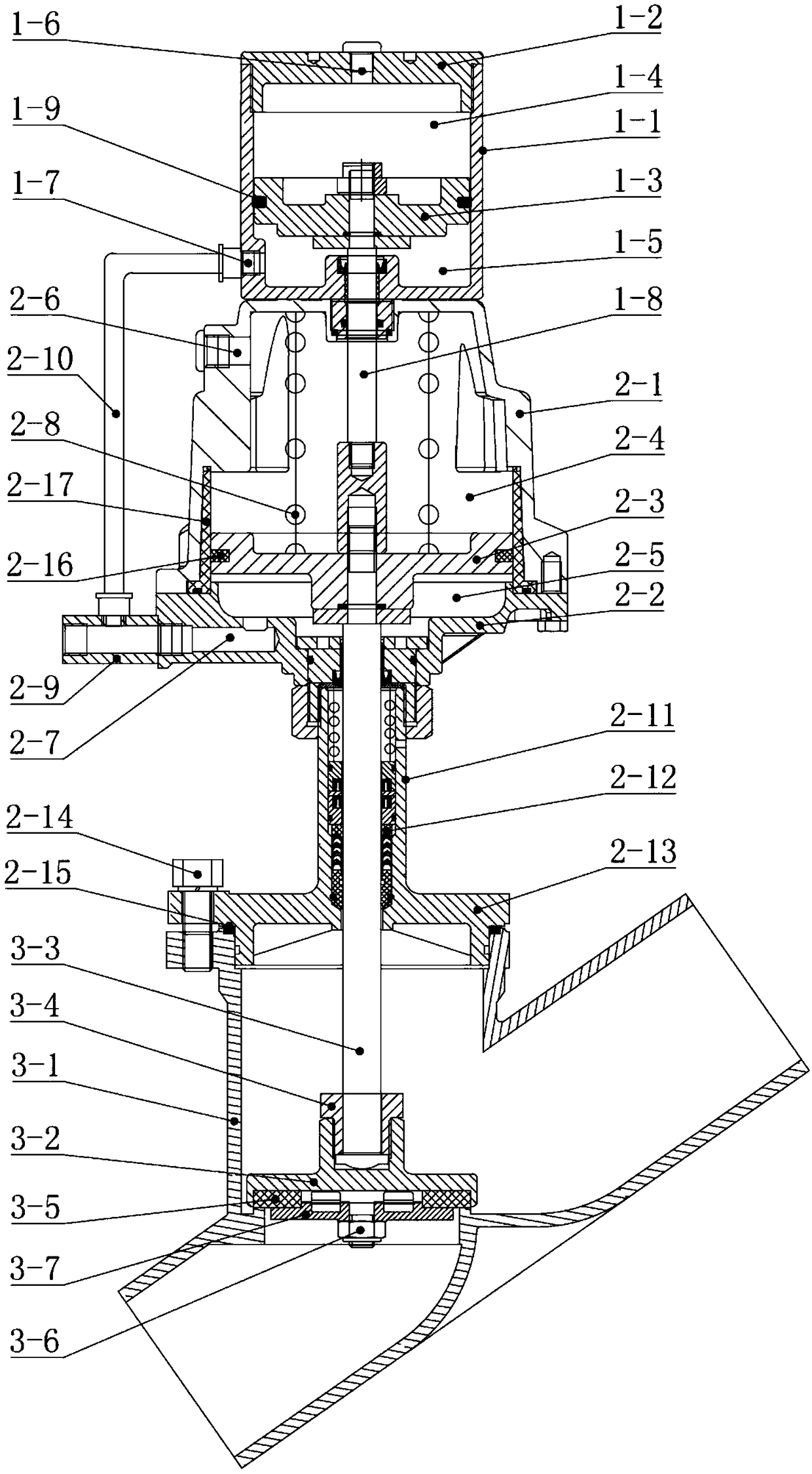
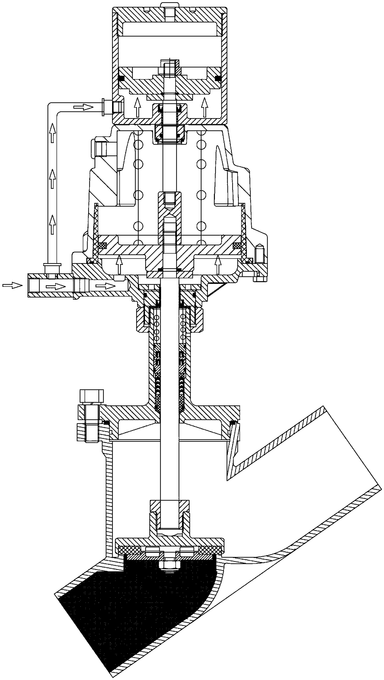
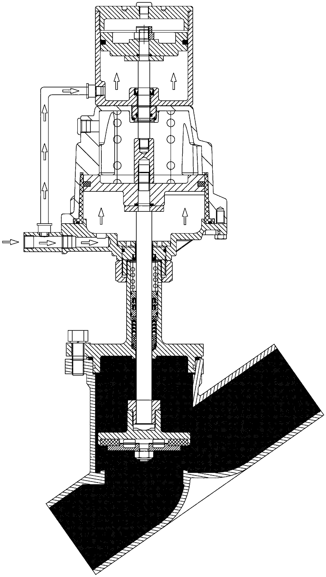
[0029] Such as figure 1 As shown, the present embodiment specifically includes a top air control mechanism 1, a middle air control mechanism 2 and a bottom actuator 3;

[0030] The top air control mechanism 1 includes the first cylinder 1-1 with the opening facing upward, the valve cover 1-2 that seals the opening, and the first piston that slides in the first cylinder 1-1 along the axial direction of the valve stem 3-3. 1-3, the outer circumference of the first piston 1-3 is provided with a circle of first piston ring 1-9, and the first piston 1-3 is in contact with the inner wall of the first cylinder 1-1 through the first piston ring 1-9, The first piston 1-3 separates the first cylinder 1-1 into a first air control chamber 1-4 and a second air control chamber 1-5 which are sealed and isolated from each other. The valve cover exhaust hole 1-6 commu...


PUM


Abstract

The invention provides a pneumatic control angle seat valve with small pneumatic control force and relates to the technical field of valves. The pneumatic control angle seat valve comprises a valve body, a valve core, a valve rod and a pneumatic valve control device, wherein the valve core and the valve rod are arranged in the valve body; the pneumatic valve control device is connected with the valve rod; four pneumatic control cavities sealed and isolated from one another are formed in the pneumatic valve control device; the pneumatic control cavities comprise a first pneumatic control cavity, a second pneumatic control cavity, a third pneumatic control cavity and a fourth pneumatic control cavity which are sequentially arranged from top to bottom along an axial direction of the valve rod; the second pneumatic control cavity is communicated with the fourth pneumatic control cavity; a first piston is arranged between the first pneumatic control cavity and the second pneumatic control cavity along the axial direction of the valve rod in a sliding manner; a second piston is arranged between the third pneumatic control cavity and the fourth pneumatic control cavity along the axial direction of the valve rod in a sliding manner; the first piston is fixedly connected with the second piston; the second piston is connected with the valve rod; a reset spring connected with the first piston or the second piston is arranged in the pneumatic valve control device. According to the pneumatic control angle seat valve disclosed by the invention, the top power-assisted pneumatic control part is increased, so that weak valve control force can be realized, and problems existing in the traditional pneumatic control angle seat valve are solved.

Description

technical field [0001] The invention relates to the technical field of valves, in particular to an air-controlled angle seat valve with a smaller air-control force. Background technique [0002] The automatic control valve greatly reduces the manual operation and reduces the production cost; the programmed operation reduces the influence of misoperation caused by human factors. Automatic valves are more and more widely accepted and applied by enterprises. [0003] Nowadays, domestic air control angle seat valve products have been widely used, but there is a common problem that the reverse pressure holding and air control pressure are contradictory, that is, the pressure required for reverse pressure holding is increasing, while the air control part The control force cannot be provided higher, so that the current solution can only use a larger volume cylinder to meet the insufficient air control force, but this will cause the valve to be bulky, resulting in the need to incre...

Claims


Application Information

Patent Timeline
Patent Type & Authority Applications(China)
IPC IPC(8): F16K17/04F16K1/48F16K27/02F16K31/122
CPCF16K17/04F16K1/482F16K27/02F16K31/1221
Inventor 张文利王伟宋洪伟
Owner QINGDAO ELITE MACHINERY MFR
Learn More