
Oil collecting box of integrated stove and manufacturing method thereof

A technology integrating stoves and oil collection boxes, applied in applications, household stoves, household heating, etc., can solve the problems of shortening the service life of oil quantity reminder devices, metal parts being easily contacted with water, and oil collection boxes being inconvenient to clean, etc. Circuit control device, increased strength, simple steps effect

Active Publication Date: 2018-09-25
浙江蓝炬星电器有限公司
View PDF7 Cites 3 Cited by
  • Summary
  • Abstract
  • Description
  • Claims
  • Application Information

AI Technical Summary

Problems solved by technology

[0002] Most of the integrated cooker oil collection boxes on the market are placed at the bottom of the integrated cooker, which is outside the normal visual range of the user, which may easily cause the user to misjudge the accumulation of oil dirt in the oil collection box, and then cause the oil box to not be dumped in time. Grease spills, adding unnecessary trouble to the user
[0003] With the development of technology, some oil collection boxes with oil quantity reminder devices have also appeared in the prior art, but these oil collection boxes are not easy to clean, and metal parts are easy to contact with water, which greatly shortens the service life of the oil quantity reminder device

Method used


Image

  • Oil collecting box of integrated stove and manufacturing method thereof
  • Oil collecting box of integrated stove and manufacturing method thereof
  • Oil collecting box of integrated stove and manufacturing method thereof

Examples


Embodiment Construction

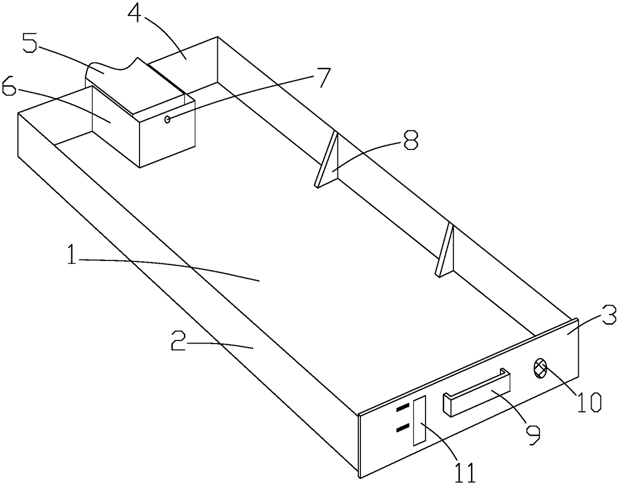
[0043] Such as Figure 1 to Figure 6As shown, it is an oil collection box for an integrated stove according to the present invention, which includes a bottom plate 1, a front plate 3, a rear plate 4 and side plates 2, and the front plate 3, the rear plate 4 and two side plates 2 are all located on the top of the bottom plate 1 On the surface, and the end to end connection forms a closed structure, and a reinforcing rib 8 is arranged between the side plate 2 and the bottom plate 1. The design of the reinforcing rib 8 greatly improves the strength of the oil collecting box and prolongs the service life of the oil collecting box.

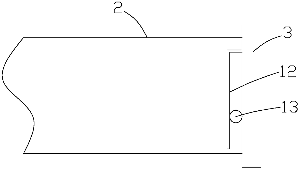
[0044] Handrail 9 is arranged on the outer surface of front plate 3, and observation window 11 and buzzer 10 are arranged on the outer surface of front plate 3, and observation window 11 and buzzer 10 are positioned at the both sides of handrail 9, and the inside of front plate 3 Hollow frame 12 is arranged on the side, and floating ball 13 is arranged...


PUM


Abstract

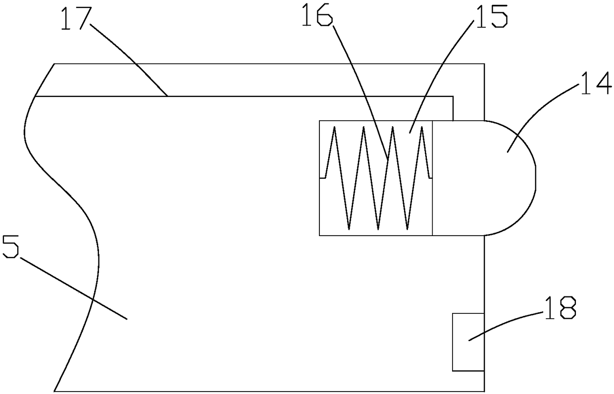
The invention discloses an oil collecting box of an integrated stove and a manufacturing method thereof. The oil collecting box comprises a bottom plate, a front plate, a rear plate and a side plate,wherein an observation window and a buzzer are arranged on the outer side of the front plate, a hollow frame is arranged on the inner surface of the front plate, a floating ball is arranged between the hollow frame and the observation window, the center of the rear plate is provided with a groove, a limiting block is arranged on the integrated stove, a liquid level sensor is arranged on a side, close to the front plate, of the groove, a first limiting slot is arranged on the limiting block, a second limiting slot is arranged on the groove, a circuit control device is arranged between the groove and the limiting block, and a sealing device is arranged on the second limiting slot. The manufacturing method comprises the steps of injection molding, circuit control device installation, sealingdevice installation, front plate processing installation, and oil collection box installation test. The manufacturing method disclosed by the invention has simple steps and strong operability, and greatly improves the production efficiency of oil collecting boxes, and the manufactured oil collecting bo can perform automatic alarm to prevent an overflow phenomenon caused by the fact that oil stains are not cleaned in time.

Description

technical field [0001] The invention relates to an oil collecting box for an integrated stove and a manufacturing method thereof. Background technique [0002] Most of the integrated cooker oil collection boxes on the market are placed at the bottom of the integrated cooker, which is outside the normal visual range of the user, which may easily cause the user to misjudge the accumulation of oil dirt in the oil collection box, and then cause the oil box to not be dumped in time. The overflow of grease will add unnecessary trouble to the user. [0003] With the development of technology, some oil collection boxes with oil volume reminder devices have also appeared in the prior art, but these oil collection boxes are not easy to clean, and metal parts are easy to contact with water, which greatly shortens the service life of the oil volume reminder device. Contents of the invention [0004] The purpose of the present invention is to provide a technical scheme of an integrate...

Claims


Application Information

Patent Timeline
Patent Type & Authority Applications(China)
IPC IPC(8): F24C15/20
CPCF24C15/20
Inventor 钱松良
Owner 浙江蓝炬星电器有限公司
Learn More