Radar antenna received signal preprocessing device and preprocessing method

A preprocessing device and technology for receiving signals, applied in electromagnetic transceivers, radio wave measurement systems, instruments, etc., can solve the problems of insufficient magnification, small magnification, and increase the noise coefficient of large signals, achieving simple structure and easy implementation. , the effect of fine control

Active Publication Date: 2018-09-25
NO 34 RES INST OF CHINA ELECTRONICS TECH GRP
View PDF7 Cites 2 Cited by
  • Summary
  • Abstract
  • Description
  • Claims
  • Application Information

AI Technical Summary

Problems solved by technology

The advantage of the first method is that the entire system will not be saturated when receiving a large signal, and avoid nonlinearity and signal distortion caused by saturation when the entire system receives a large signal; but because the amplifier multiple of this method is based on the large signal Designed, the magnification is relatively small, so when the received signal power is low, the magnification is not enough, affecting the dynamic range of the entire system
The advantage of the second method is that the large signal is attenuated by the numerically controlled attenuator to avoid nonlinearity and signal distortion caused by saturation, but after the large signal is attenuated by the numerically controlled attenuator, the noise figure of the large signal will be increased

Method used


Image

  • Radar antenna received signal preprocessing device and preprocessing method

Examples


Embodiment Construction

[0034] Embodiment of Radar Antenna Received Signal Preprocessing Device

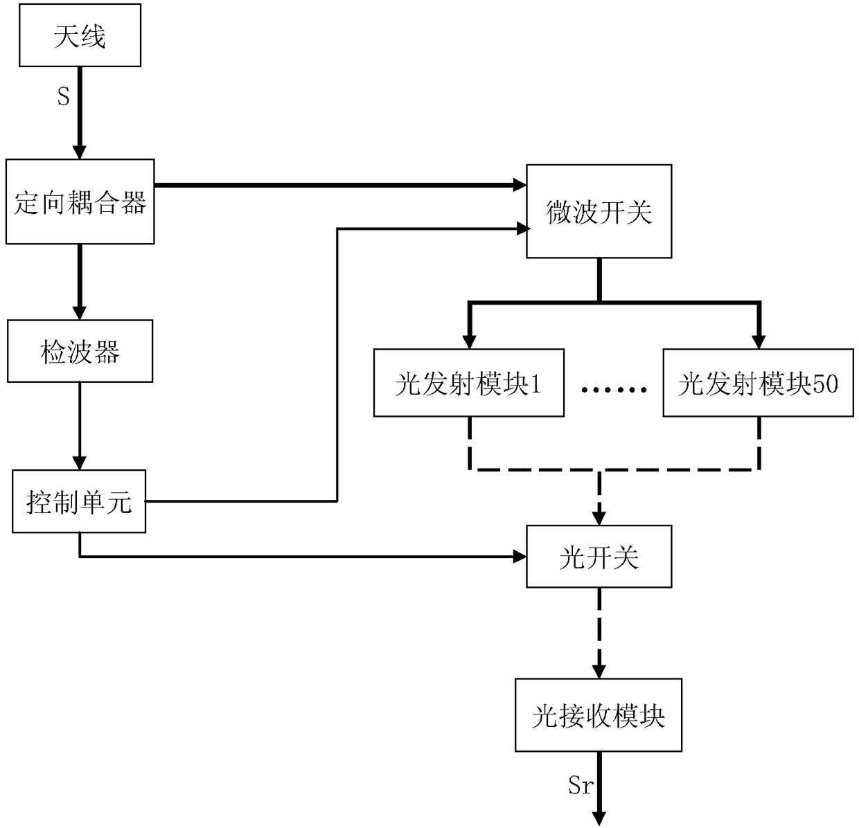
[0035] The embodiment of the radar antenna receiving signal preprocessing device is for example figure 1 As shown, it includes an antenna and an optical transmitting module. The optical transmitting module contains an amplifier and a photoelectric converter. The converted optical signal is connected to one end of the transmission fiber, and the other end of the transmission fiber is connected to the optical receiving module.

[0036] The microwave signal received by the antenna (indicated by a thick solid line in the figure) is connected to the directional coupler. The splitting ratio of the directional coupler in this example is 1 / 20, that is, 20 parts of the microwave signal are connected to the microwave switch, and 1 part of the microwave signal is connected to the A detector that detects the power of a microwave signal. The detection signal of the detector is connected to the control unit, and the ...


PUM


Abstract

The invention relates to a radar antenna received signal preprocessing device and preprocessing method. The device is additionally provided with a directional coupler, a detector, a microwave switch,an optical switch and a control unit, and is provided with n light emitting modules, amplifiers of the light emitting modules have different magnification times, which correspond to different power intervals of microwave signals. According to the processing method, microwave signals received by an antenna are divided into two paths by the directional coupler, the majority of the microwave signalsenters the microwave switch, and a small part of the microwave signals enters the detector to detect a power value. The control unit selects the light emitting module corresponding to the magnification times of the corresponding power interval according to the current signal power value depending on the detection result, controls the microwave switch to access the current microwave signal, and controls the optical switch to connect an output end of the selected light emitting module to a transmission optical fiber; the microwave signals are amplified and converted into optical signals; and theoptical signals are sent to a light receiving module by the transmission optical fiber. The magnification times are selected according to the signal power, the large signal does not need to be attenuated, and the small signal has a large amplification rate, thereby ensuring the dynamic range of the entire radar system.

Description

technical field [0001] The invention relates to the technical field of radar receiving, in particular to a radar antenna receiving signal preprocessing device and a preprocessing method. Background technique [0002] Radar and antennas are widely used in modern communication systems. There is a certain distance between radar and antenna and the central computer room. However, in some actual situations, the distance between the radar, antenna, etc. and the central computer room is relatively long, some are several kilometers away, and some are even tens of kilometers away. In the case of a long distance, the loss of the radar signal transmission in the cable is very large, and it needs to be transmitted by optical fiber. In this way, signals received by radars, antennas, etc. are usually amplified and then converted into optical signals for transmission. Since the amplitude of the signal received by the radar, antenna, etc. fluctuates, the signal power is uncertain. The ex...

Claims


Application Information

Patent Timeline
Patent Type & Authority Applications(China)
IPC IPC(8): H04B10/40G01S7/02
CPCH04B10/40G01S7/02
Inventor 黄锋锋臧习飞席虹标陈国帅吴见平熊平戬
Owner NO 34 RES INST OF CHINA ELECTRONICS TECH GRP
Why Eureka
Try Eureka