Intermittent glue filling device for automatic glue filling of wire harness terminal

A wire harness terminal, intermittent technology, applied in the field of intermittent glue filling device, can solve the problems of large equipment volume and complex structure of glue dispensing device, and achieve the effect of compact structure

Inactive Publication Date: 2018-09-28
WUHU BOKANG ELECTRICAL
View PDF5 Cites 0 Cited by
  • Summary
  • Abstract
  • Description
  • Claims
  • Application Information

AI Technical Summary

Problems solved by technology

[0004] Although the above-mentioned device can realize dispensing work, its dispensing device has a complex structure and a large equipment volume

Method used


Image

  • Intermittent glue filling device for automatic glue filling of wire harness terminal
  • Intermittent glue filling device for automatic glue filling of wire harness terminal

Examples


Embodiment 1

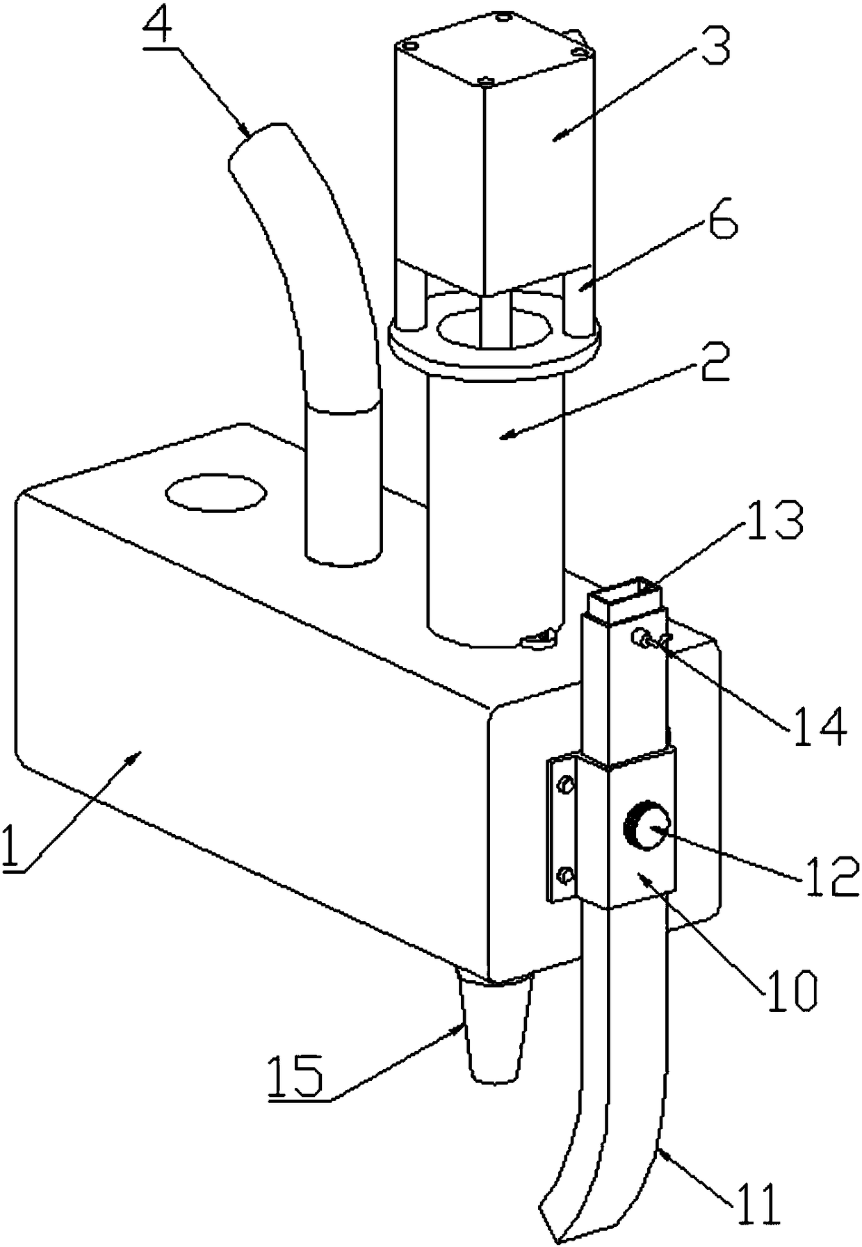
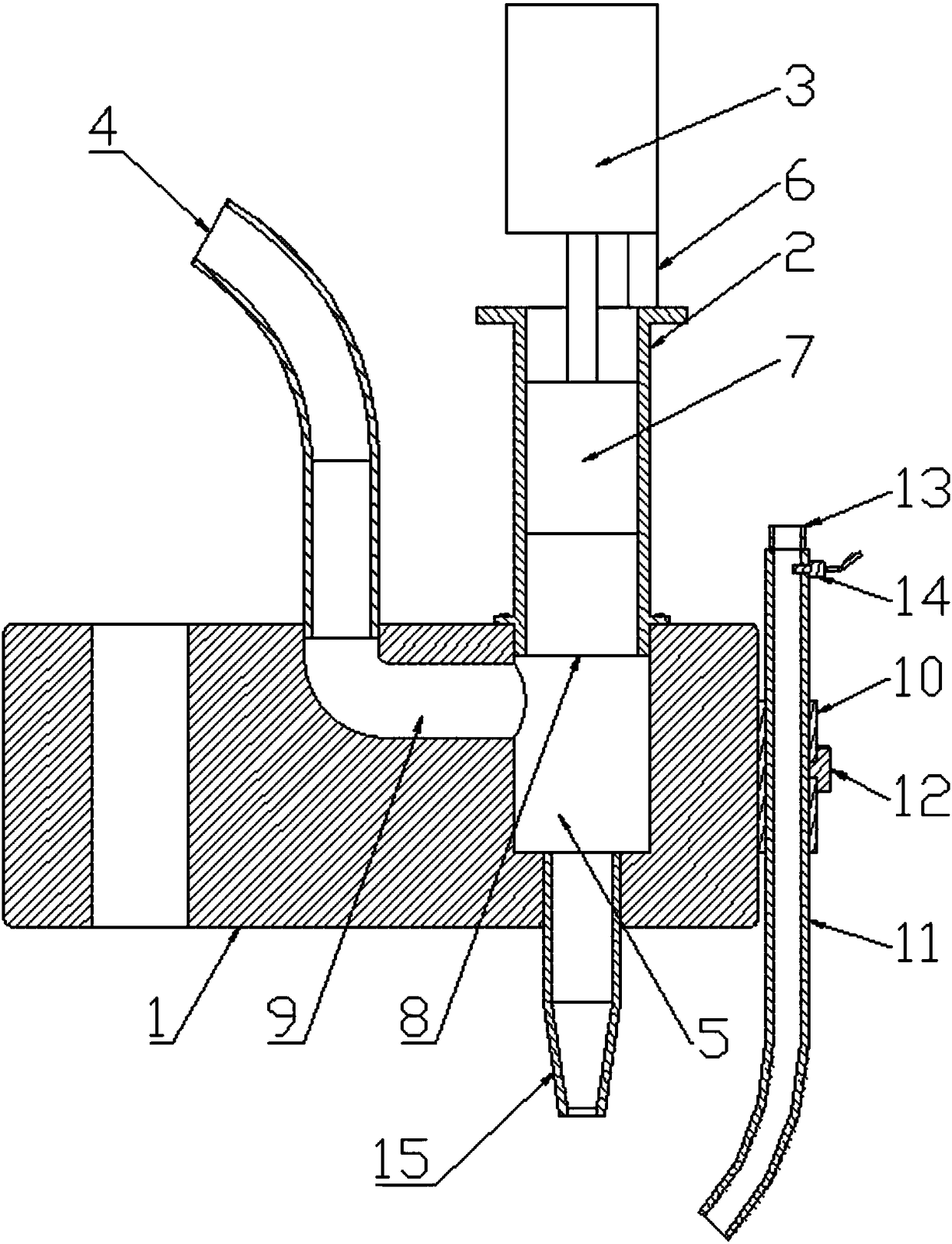
[0019] like figure 1 and figure 2 As shown, an intermittent glue filling device for automatic glue filling of wire harness terminals, including a body 1, a piston barrel 2, a cylinder 3 and a rubber delivery tube 4, a fluid channel 5 is provided in the body 1, and the piston barrel 2 is installed in the fluid channel 5 On the body 1 directly above, the top of the piston cylinder 2 is also provided with a support tube 6, the cylinder 3 is installed on the top of the support tube 6, the output shaft of the cylinder 3 is connected to the piston 7, and the piston 7 is slidably connected in the piston cylinder 2 , and the glue storage chamber 8 is formed between the bottom surface of the piston 7 and the bottom surface of the fluid channel 5, the bottom of the fluid channel 5 is connected with a glue filling pipe 15, and the body 1 is also provided with a glue filling flow channel 9, and the lower end of the glue filling flow channel 9 It communicates with the fluid passage 5, th...

Embodiment 2

[0024] like figure 1 and figure 2 As shown, an intermittent glue filling device for automatic glue filling of wire harness terminals, including a body 1, a piston barrel 2, a cylinder 3 and a rubber delivery tube 4, a fluid channel 5 is provided in the body 1, and the piston barrel 2 is installed in the fluid channel 5 On the body 1 directly above, the top of the piston cylinder 2 is also provided with a support tube 6, the cylinder 3 is installed on the top of the support tube 6, the output shaft of the cylinder 3 is connected to the piston 7, and the piston 7 is slidably connected in the piston cylinder 2 , and the glue storage chamber 8 is formed between the bottom surface of the piston 7 and the bottom surface of the fluid channel 5, the bottom of the fluid channel 5 is connected with a glue filling pipe 15, and the body 1 is also provided with a glue filling flow channel 9, and the lower end of the glue filling flow channel 9 It communicates with the fluid passage 5, th...


PUM


Abstract

The invention discloses an intermittent glue filling device for automatic glue filling of a wire harness terminal and relates to the technical field of wire harness processing. The intermittent glue filling device comprises a machine body, a piston cylinder, an air cylinder and a glue transmission pipe, wherein a fluid channel is arranged in the machine body; the piston cylinder is mounted on themachine body right above the fluid channel; a support pipe is further arranged at the top of the piston cylinder; the air cylinder is mounted at the top of the support pipe; the output shaft of the air cylinder is connected with a piston; the piston is in sliding fit with the interior of the piston cylinder; a glue storage cavity is formed between the bottom surface of the piston and the bottom surface of the fluid channel; the bottom of the fluid channel is connected with a glue filling pipe; a glue filling passageway is further arranged in the machine body; the lower end of the glue fillingpassageway communicates with the fluid channel; the upper end of the glue filling passageway communicates with the glue transmission pipe; and the other end of the glue transmission pipe is connectedonto a glue source. According to the intermittent glue filling device, glue filling is realized when the air cylinder stretches out and draws back to and fro; in addition, the flowing channel of the glue source is arranged in the machine body, so that the intermittent glue filling device is more compact in structure; and the glue filling passageway adopts curve design to enable glue to circulate smoothly.

Description

technical field [0001] The invention relates to the technical field of wire harness processing, in particular to an intermittent glue filling device for automatic glue filling of wire harness terminals. Background technique [0002] In wire harness processing, there are two main purposes of gluing. One is bonding. The bonding mainly considers the bonding strength. After bonding, whether the position of the glue will cause structural interference and make assembly difficult; the other is sealing. Water resistance, if the device does not leak, the waterproof performance is good, and if the device leaks, the waterproof performance is not good. At present, the dispensing (or glue filling) of the wire harness terminal is to manually insert the wire harness terminal into a fixed tooling, and then manually dispense the glue, which is inefficient. [0003] Chinese Patent Publication No. CN207119511U discloses an automatic glue dispensing device for automobile wiring harness process...

Claims


Application Information

Patent Timeline
IPC IPC(8): B05C5/02B05C11/10
Inventor 朱磊马能发李华郑凯邱亮亮施其兵方良周前宽张冲张静冯瑞叶立新张建军杨开文
Owner WUHU BOKANG ELECTRICAL
Why Eureka
Try Eureka