Automatic chuck for small hardware grinding machine

A hardware and grinding machine technology, which is applied in the direction of grinding machines, grinding workpiece supports, metal processing equipment, etc., can solve the problems of reducing the clamping stability of grinding machines, reducing the accuracy of workpieces, and low positioning accuracy, so as to improve applicability and Positioning accuracy, improved clamping stability, and good clamping stability

Inactive Publication Date: 2018-09-28
湖州铭之远研磨科技有限公司
View PDF8 Cites 2 Cited by
  • Summary
  • Abstract
  • Description
  • Claims
  • Application Information

AI Technical Summary

Problems solved by technology

However, because the current grinding machine generally uses a three-jaw chuck to fix the workpiece, the grinding machine cannot fix some workpieces with unconventional shapes, and it will also cause asymmetrical parts such as oval parts and eccentric tubes when fixing The three jaws of the chuck cannot form a tight fit on the workpiece at the same time, thus reducing the clamping stability of the grinding machine to the workpiece
In addition, because the conventional grinding machine cannot rotate and tilt the workpiece after clamping, the grinding machine needs to repeatedly position the workpiece during the multiple grinding process of a workpiece. When the workpiece needs to be ground in an inclined position It can only be done by changing the clamping position of the workpiece. This positioning and adjustment method will not only reduce the accuracy of the workpiece after grinding, but also reduce the clamping stability of the grinding machine by tilting the clamping, so that the workpiece will In the process, there will be force deviation or drop, which is poor in safety
Therefore, the clamping method of the existing grinding machine to the workpiece has the problems of small application range, low positioning accuracy, and poor clamping stability

Method used


Image

  • Automatic chuck for small hardware grinding machine
  • Automatic chuck for small hardware grinding machine
  • Automatic chuck for small hardware grinding machine

Examples


Embodiment Construction

[0015] The present invention will be further described below in conjunction with the accompanying drawings and embodiments, but not as a basis for limiting the present invention.

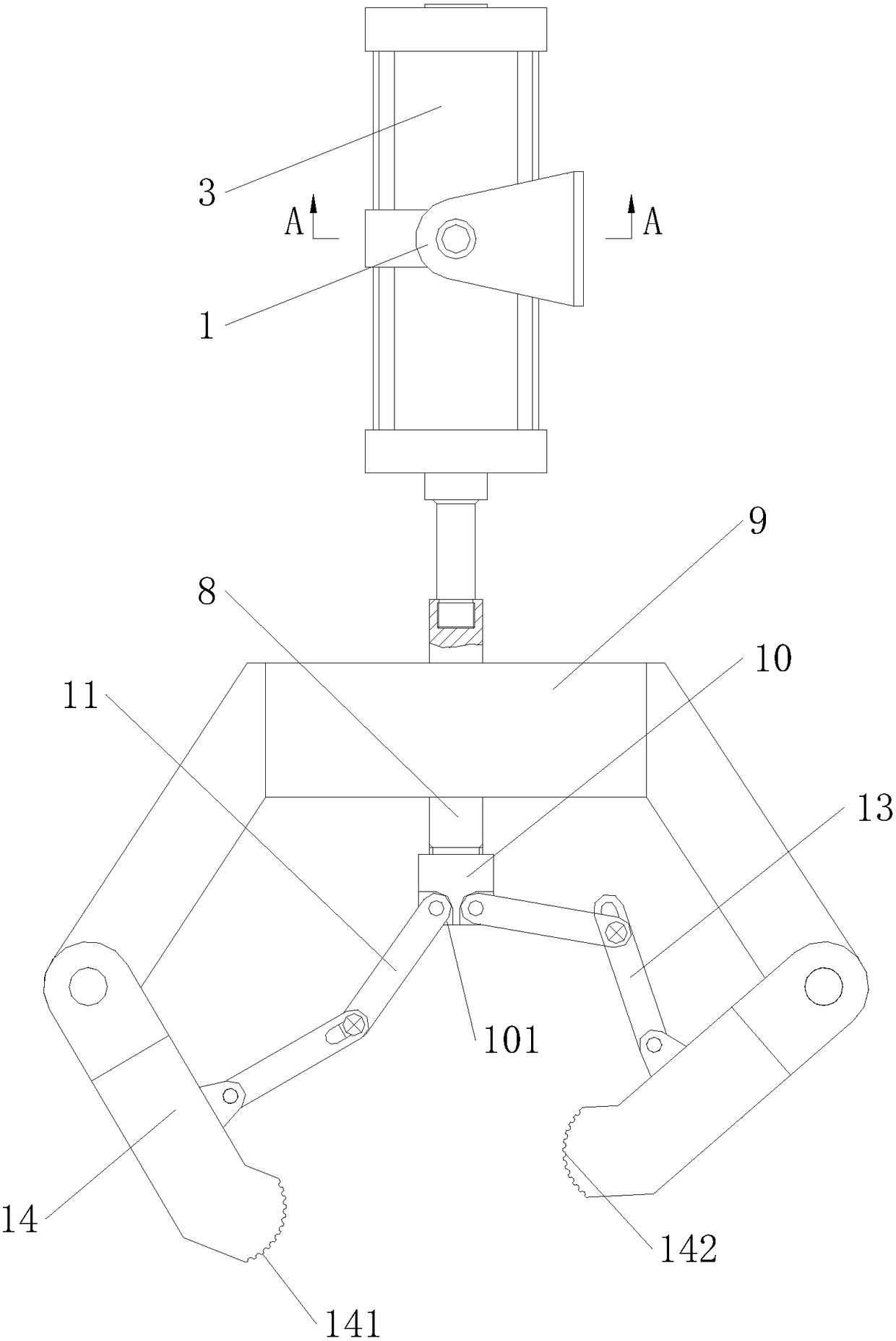
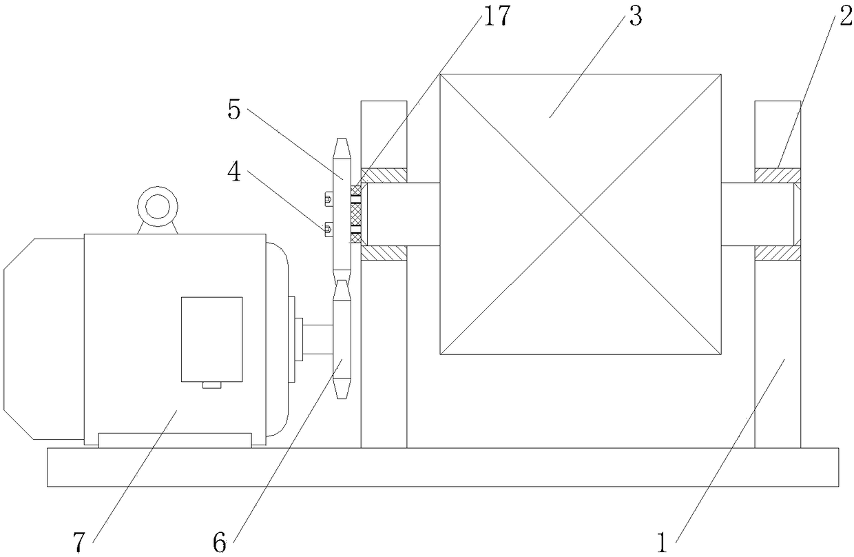
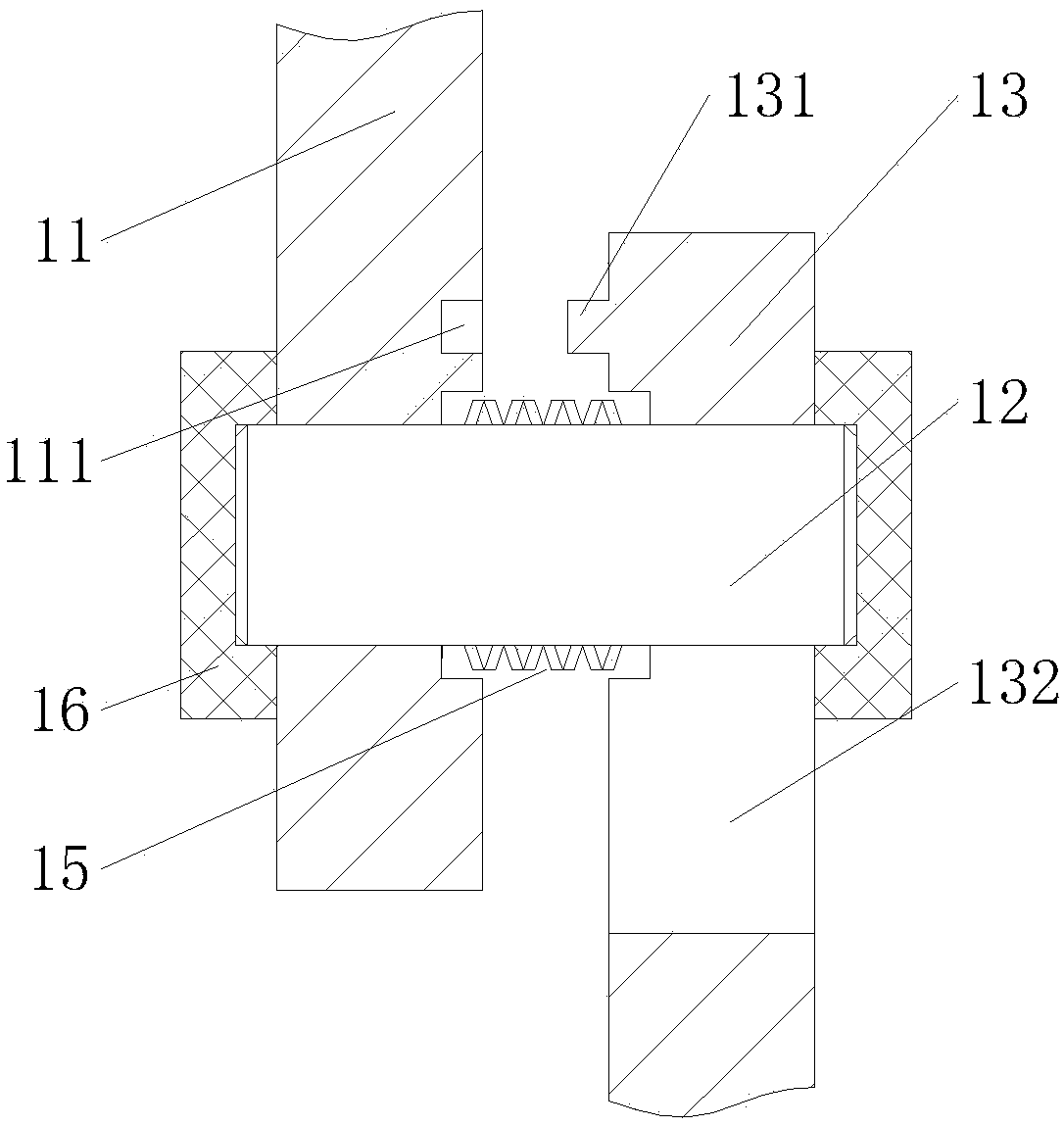
[0016] Example. An automatic chuck for a small hardware grinding machine, which is composed of figure 1 As shown, it includes a support frame 1, the support frame 1 is connected with a middle swing cylinder 3 through a copper sleeve 2, and the outside of the swing shaft on one side of the middle swing cylinder 3 is connected with a rotating gear 5 through a plurality of screws 4, and the lower end of the rotating gear 5 The driving gear 6 is engaged with the drive gear 6, the driving motor 7 is connected to the inner side of the driving gear 6, and the extension shaft of the middle swing cylinder 3 is connected to the telescopic rod 8. A rod head 10 is connected, and locking screws are arranged on the side wall of the rod head 10. A plurality of mounting steps 101 are evenly distributed on the outs...


PUM


Abstract

The invention discloses an automatic chuck for a small hardware grinding machine. The automatic chuck for the small hardware grinding machine comprises a support frame; the support frame is connectedwith a middle swing cylinder by a copper sleeve; an extension shaft of the middle swing cylinder is connected with an extension rod; a mounting frame is arranged on the outer side of the extension rod; the end part of the extension rod is in threaded connection with a rod head; multiple mounting steps are uniformly distributed on the outer side of the rod head; the outer sides of all the mountingsteps are rotationally connected with first connecting rods; the end parts of the first connecting rods are connected with second connecting rods by pin shafts; the end parts of the second connectingrods are connected with clamping plates; the other ends of the clamping plates are rotationally connected to the mounting frame; butterfly springs, positioned between the first connecting rods and thesecond connecting rods, are arranged at the middle parts of the pin shafts; and electromagnets, fixed on the outer sides of the first connecting rods and the second connecting rods, are arranged at the two ends of the pin shafts. The automatic chuck for the small hardware grinding machine has the characteristics of wide application range, high positioning precision and good clamping stability.

Description

technical field [0001] The invention relates to an automatic chuck for a grinding machine, in particular to an automatic chuck for a small hardware grinding machine. Background technique [0002] The function of the small hardware grinding machine is to clamp and fix the small workpiece, and then grind the surface or sharp corners of the workpiece through the grinding head, so as to complete the shape of the small workpiece and make the grinding surface have a high degree of smoothness. However, because the current grinding machine generally uses a three-jaw chuck to fix the workpiece, the grinding machine cannot fix some workpieces with unconventional shapes, and it will also cause asymmetrical parts such as oval parts and eccentric tubes when fixing The three jaws of the chuck cannot form a tight fit on the workpiece at the same time, thereby reducing the clamping stability of the grinding machine to the workpiece. In addition, because the conventional grinding machine ca...

Claims


Application Information

Patent Timeline
IPC IPC(8): B24B19/00B24B41/06
CPCB24B19/00B24B41/06
Inventor 赵剑波
Owner 湖州铭之远研磨科技有限公司
Why Eureka
Try Eureka