Concrete block forming machine

A technology of concrete blocks and concrete blocks, which is applied to ceramic molding machines, grinding racks, and parts of grinding machine tools, etc., can solve problems such as easy dumping of concrete blocks, low cleaning efficiency, and damage to concrete blocks, and achieve Reduce the cost of manual cleaning, increase work efficiency, and increase the effect of grinding efficiency

Pending Publication Date: 2018-09-28
CHINA CONSTR EIGHTH ENG DIV
View PDF0 Cites 1 Cited by
  • Summary
  • Abstract
  • Description
  • Claims
  • Application Information

AI Technical Summary

Problems solved by technology

[0003] The existing concrete block forming machine is equipped with a conveying platform at the outlet to convey the formed concrete blocks. The existing conveying platform has a relatively simple structure, which makes the formed concrete blocks prone to dumping during the conveying process, resulting in concrete The block is damaged, and at the same time, a large amount of waste remains on the concrete block after the concrete block forming machine is processed. Usually, it is cleaned manually, the cleaning efficiency is low, and the cost is increased. Therefore, the conveying platform structure of the concrete block forming machine needs to be improved.

Method used


Image

  • Concrete block forming machine
  • Concrete block forming machine
  • Concrete block forming machine

Examples


Embodiment Construction

[0020] The following will clearly and completely describe the technical solutions in the embodiments of the present invention with reference to the accompanying drawings in the embodiments of the present invention. Obviously, the described embodiments are only some, not all, embodiments of the present invention. Based on the embodiments of the present invention, all other embodiments obtained by persons of ordinary skill in the art without making creative efforts belong to the protection scope of the present invention.

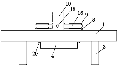
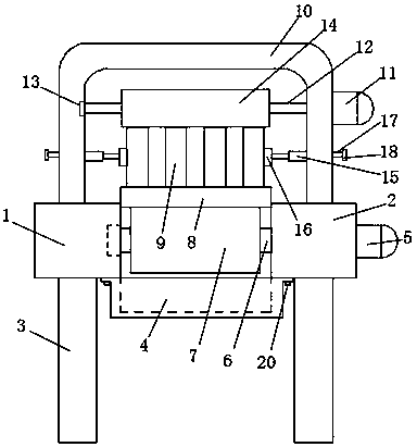
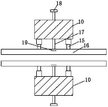
[0021] see Figure 1-3 , the present invention provides a technical solution: a concrete block forming machine, comprising a left fixed plate 1 and a right fixed plate 2, legs 3 are fixedly installed on both sides of the lower surface of the left fixed plate 1 and the right fixed plate 2, and the left and right fixed plates 2 The bottom of the fixed plate 1 and the right fixed plate 2 is threadedly connected with a storage box 4 by a screw 20. The storage box ...


PUM


Abstract

The invention discloses a concrete block forming machine. The concrete block forming machine comprises a left fixing plate and a right fixing plate, and the two sides of the lower surfaces of the leftfixing plate and the right fixing plate are fixedly provided with supporting legs. The lower portions of the left fixing plate and the right fixing plate are in threaded connection with a storage boxthrough bolts, and waste residues generated after concrete blocks are polished are collected by the storage box conveniently. A rotary pillar is wound with a conveyer belt, a first motor drives the rotary pillar and the conveyer belt to rotate conveniently, and a placement plate is made to drive the upper portions of the concrete blocks to be polished. The two sides on the opposite faces of a fixing rack are connected with limiting plates through telescopic rods, and the telescopic rods achieve supporting and guiding effects on the limiting plates. The two sides of the fixing rack are in threaded connection with threaded rods, the limiting plates can move towards the concrete blocks through the threaded rods, the limiting plates play a limiting role in the concrete blocks, the concrete blocks are not prone to topple and fall, and the polishing efficiency of the concrete blocks is improved.

Description

technical field [0001] The invention relates to the technical field of concrete forming machines, in particular to a concrete block forming machine. Background technique [0002] Concrete block forming machine is a machine for producing blocks. The new wall is mainly made of blocks and cement bricks. Most of them adopt hydraulic forming mode, and some use vibration forming, but there are few of them. With the user's quality With the improvement of production efficiency requirements, the demand for concrete block forming machines is also increasing. In order to improve production efficiency, the forming mold is usually equipped with multiple forming cavities, which can produce multiple blocks at the same time. [0003] The existing concrete block forming machine is equipped with a conveying platform at the outlet to convey the formed concrete blocks. The existing conveying platform has a relatively simple structure, which makes the formed concrete blocks prone to dumping duri...

Claims


Application Information

Patent Timeline
Patent Type & Authority Applications(China)
IPC IPC(8): B24B27/033B24B41/00B24B55/06B24B41/02B28B11/22
CPCB24B27/033B24B41/005B24B41/02B24B55/06B28B11/22
Inventor 马海龙
Owner CHINA CONSTR EIGHTH ENG DIV
Why Eureka
Try Eureka