Rubber piece automatic reverse head-delivery equipment

A technology of automatic reverse and equipment, applied in the direction of tires, other household appliances, household appliances, etc., can solve the problems of film accuracy, inconvenient operation, manual operation instability, etc., to achieve the effect of ensuring accuracy

Pending Publication Date: 2018-09-28
TIANJIN VOCATIONAL & TECHNICAL COLLEGE OF MECHANICAL & ELECTRICAL ENG
View PDF0 Cites 6 Cited by
  • Summary
  • Abstract
  • Description
  • Claims
  • Application Information

AI Technical Summary

Problems solved by technology

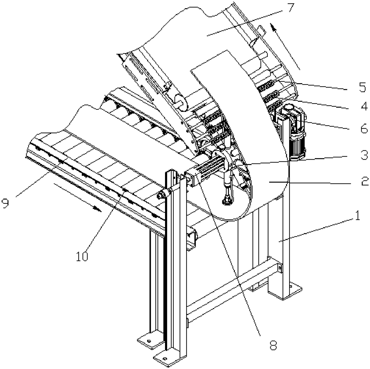
[0002] In the process of material transportation, sometimes according to production needs or space requirements, materials are required to be reversely conveyed. For example, in the tire production process, the film cooling production line, film cooling is mainly realized by spraying or soaking, and the cooling device is divided into multiple sections of independent conveying mechanism, and the multi-stage conveying mechanism is stacked up and down, for example, it includes a horizontally arranged conveying mechanism and an uphill conveying mechanism directly above it. The film is input by the horizontally arranged conveying mechanism, and then output by the uphill conveying mechanism. When the discharge end goes to the feed end of another conveying mechanism, it is necessary to manually transfer the head to guide the material. The material transfer method of this structure is often limited by the space of the support frame, which is inconvenient to operate, and the manual transfer also has potential safety hazards. At the same time, the manual transfer method Due to the instability of manual operation, it is easy to have a certain impact on the accuracy of the film due to the change of the film delivery position

Method used


Image

  • Rubber piece automatic reverse head-delivery equipment
  • Rubber piece automatic reverse head-delivery equipment
  • Rubber piece automatic reverse head-delivery equipment

Examples


Embodiment Construction

[0035] It should be noted that the embodiments of the present invention and the features of the embodiments may be combined with each other under the condition of no conflict.

[0036] In the description of the present invention, it should be understood that the terms "center", "portrait", "horizontal", "top", "bottom", "front", "rear", "left", "right", " The orientation or positional relationship indicated by vertical, horizontal, top, bottom, inner, outer, etc. is based on the orientation or positional relationship shown in the drawings, and is only for the convenience of describing the present invention and The description is simplified rather than indicating or implying that the device or element referred to must have a particular orientation, be constructed and operate in a particular orientation, and therefore should not be construed as limiting the invention. In addition, the terms "first", "second", etc. are used for descriptive purposes only, and should not be constru...


PUM


Abstract

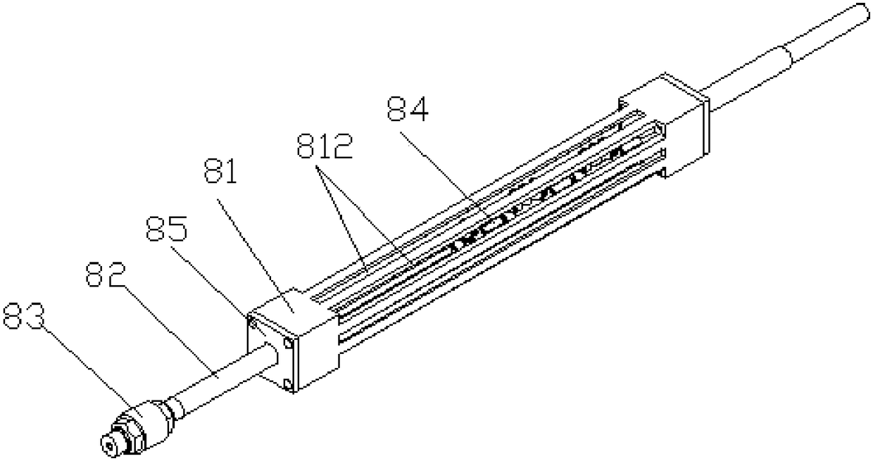
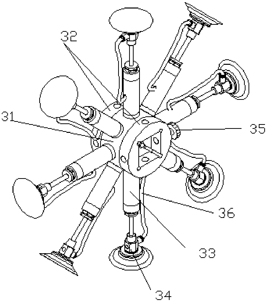
The invention provides rubber piece automatic reverse head-delivery equipment. The rubber piece automatic reverse head-delivery equipment is arranged between the discharging end of a horizontal conveying mechanism and the feeding end of an uphill conveying mechanism and comprises a bracket, a gas supply shaft, and a material picking and conveying device for picking materials of the horizontal conveying mechanism and reversely conveying the materials to the uphill conveying mechanism; the material picking and conveying device comprises a shaft sleeve and a plurality of vacuum suction cups evenly arranged on the outer circumferential surface of the shaft sleeve in the circumferential direction of the shaft sleeve; the shaft sleeve is fixedly mounted on the gas supply shaft in a sleeving mode, gas inlets of the vacuum suction cups are connected with gas inlet hoses, and each gas inlet hose communicates with a gas outlet of a gas distributor. According to the rubber piece automatic reversehead-delivery equipment, the gas supply shaft drives the multiple vacuum suction cups on the shaft sleeve to rotate around the axis, thus rubber pieces are automatically transferred from the discharging end of the horizontal conveying mechanism to the feeding end of the uphill conveying mechanism, a conventional manual transferring mode is changed through the transferring mode, the material transferring process of the vacuum suction cups are completed through control of a controller, and the accuracy of the transferring position is ensured.

Description

technical field [0001] The invention belongs to the field of material reverse conveying equipment, and in particular relates to an automatic reverse feeding equipment for film. Background technique [0002] In the process of material conveying, sometimes the material is required to be conveyed in reverse according to production needs or space requirements. For example, in the tire production process, the film cooling production line and film cooling are mainly realized by spraying or soaking, and the cooling device is divided into multiple sections of independent conveying. The multi-segment conveying mechanism is placed up and down, for example, including a horizontal conveying mechanism and an uphill conveying mechanism directly above it. When the discharge end reaches the feeding end of another conveying mechanism, it needs to manually transfer the head to guide the material. The material moving method of this structure is often limited by the space of the support frame, ...

Claims


Application Information

Patent Timeline
Patent Type & Authority Applications(China)
IPC IPC(8): B29D30/00
CPCB29D30/0016B29D2030/0038
Inventor 吕炜帅李欣
Owner TIANJIN VOCATIONAL & TECHNICAL COLLEGE OF MECHANICAL & ELECTRICAL ENG
Why Eureka
Try Eureka