Supercharge Your Innovation With Domain-Expert AI Agents!

Broken yarn detection device for warp loom

A technology for yarn breakage detection and knitting machine, which is applied in knitting, textile and paper making, etc., can solve the problems of affecting the use of the detection device, contamination with dust, yarn breakage, etc., and achieves the effect of simple structure, economical and practical, and easy dust removal treatment.

Inactive Publication Date: 2018-09-28
湖州福而美针纺有限公司
View PDF1 Cites 3 Cited by
  • Summary
  • Abstract
  • Description
  • Claims
  • Application Information

AI Technical Summary

Problems solved by technology

[0002] When the warp knitting machine is used for weaving, yarn breakage often occurs. At this time, the warp knitting machine needs to be stopped in time to avoid defects on the cloth surface. After retrieval, the authorized announcement number is CN204342170U, which discloses a textile machine Yarn breakage detection device. When the yarn breakage detection device is installed and used, when the yarn breaks, the power-off hammer falls, and the conical hammer head breaks the two pieces of broken electric conductors, and the equipment stops running. At the same time, the electric conduction on the hammer handle The ring is in contact with the two alarm energizing plates, the entire alarm circuit is turned on, and the alarm sounds, thus playing the role of yarn breakage shutdown and alarm, which has a good use effect, but its detection settings will produce problems after long-term use. A large amount of heat affects the use of the detection device, and the surface of the detection device is contaminated with a lot of dust after long-term use, which is not easy to clean. Therefore, we propose a yarn breakage detection device for warp knitting machines to solve the above problems. question

Method used


Image

  • Broken yarn detection device for warp loom
  • Broken yarn detection device for warp loom
  • Broken yarn detection device for warp loom

Examples


Embodiment Construction

[0023] The technical solutions in the embodiments of the present invention will be clearly and completely described below in conjunction with the accompanying drawings in the embodiments of the present invention. Obviously, the described embodiments are only a part of the embodiments of the present invention, rather than all the embodiments.

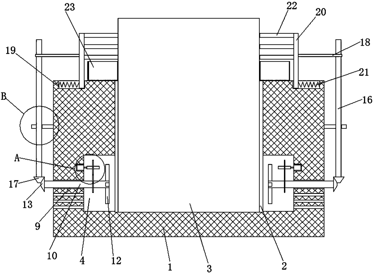
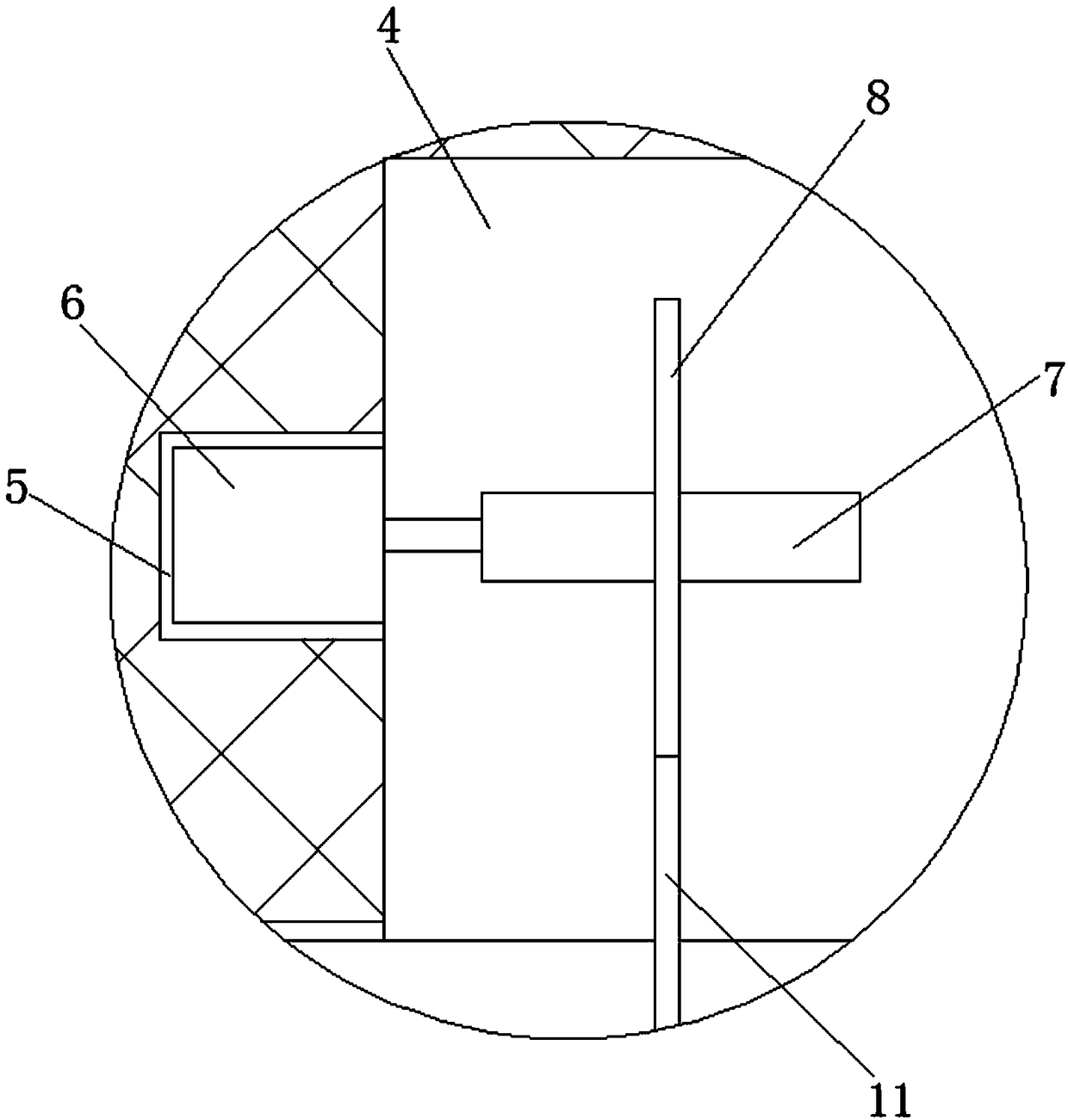
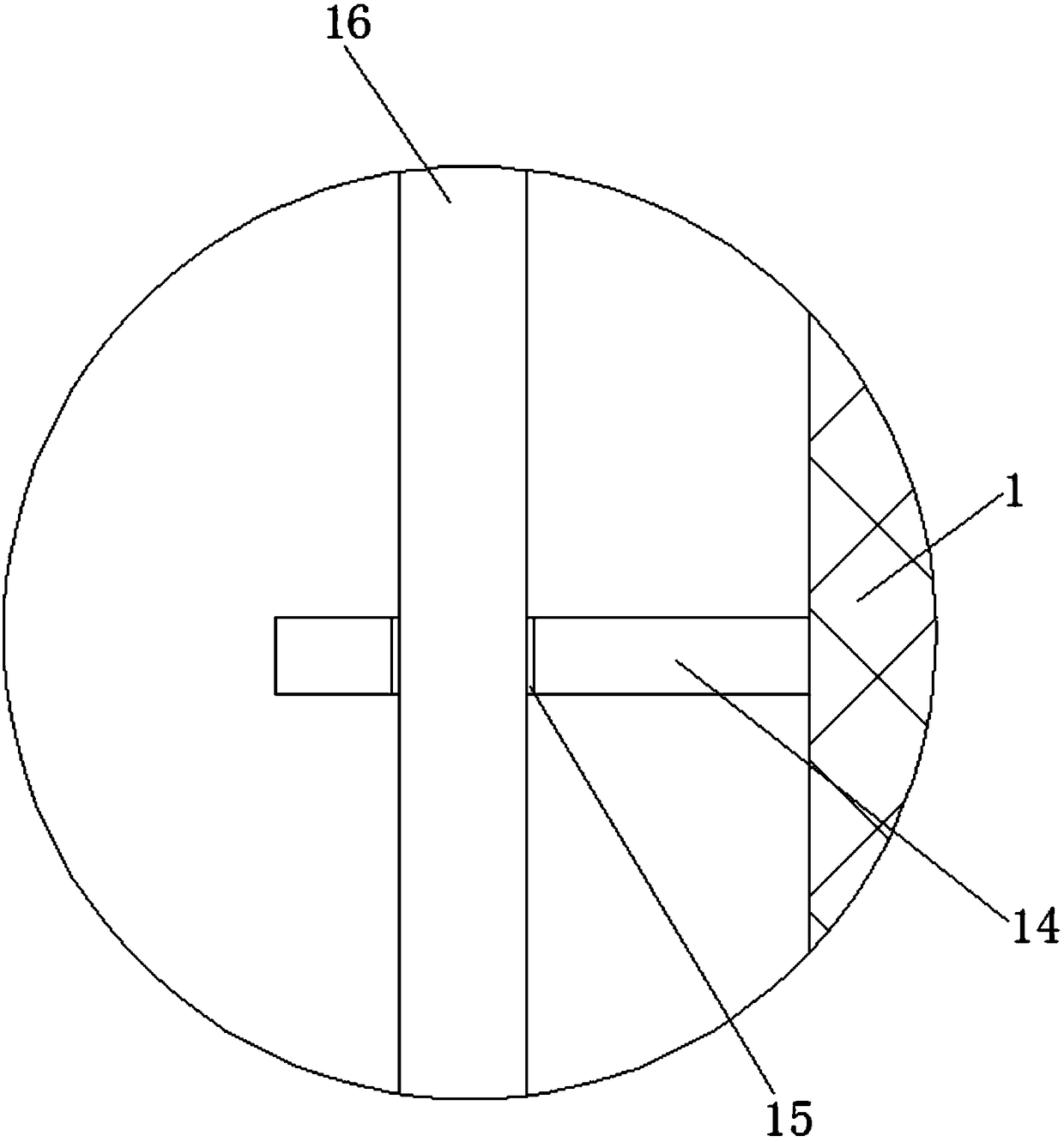
[0024] Reference Figure 1-3 , A yarn break detection device for a warp knitting machine, comprising a mounting base 1 and a first mounting slot 2 opened on the top of the mounting base 1. The first mounting slot 2 is equipped with a device body 3, and the first mounting slot 2 Rectangular grooves 4 are provided on the inner walls of both sides, and the inner walls of the two rectangular grooves 4 far away from each other are provided with a second installation groove 5, and the second installation groove 5 is installed with a drive motor 6 and the output shaft of the drive motor 6. There is a first rotating shaft 7 welded thereon, and a fi...


PUM


Abstract

The invention discloses a broken yarn detection device for a warp loom. The broken yarn detection device comprises an installation base and a first installation groove which is formed in the top of the installation base, a device body is mounted in the first installation groove, and rectangular grooves are formed in inner walls of the two sides of the first installation groove. Second installationgrooves are formed in inner walls of the sides, away from each other, of the two rectangular grooves, driving motors are mounted in the second installation grooves, first rotation shafts are welded to output shafts of the driving motors, and first gears fixedly sleeve the first rotation shafts. First rotation holes are formed in inner walls of the sides, away from each other, of the two rectangular grooves, second rotation shafts are rotatably mounted in the first rotation holes, and second gears fixedly sleeve the second rotation shafts and are meshed with the first gears. The broken yarn detection device for the warp loom is simple in structure, economical and practical, heat dissipation treatment of the device body is facilitated through the second rotation shafts and heat dissipationfan blades, and dusting treatment of the device body is facilitated through sliding columns and rubber columns.

Description

Technical field [0001] The present invention relates to the technical field of detection devices, in particular to a yarn break detection device for warp knitting machines. Background technique [0002] When the warp knitting machine is spinning, yarn breakage often occurs. At this time, it is necessary to stop the warp knitting machine in time to avoid defects on the fabric surface. After searching, the authorized announcement number CN204342170U discloses a textile machine. Yarn breakage detection device. When the yarn breakage detection device is installed and used, when the yarn breaks, the power-off hammer will fall, the tapered hammer head will disconnect the two conductive pieces, the equipment will stop running, and the hammer handle will conduct electricity. The ring is in contact with the energized pieces of the two alarms, the entire alarm circuit is turned on, and the alarm sounds, thereby playing the role of yarn breakage shutdown and alarm. It has a good use effect,...

Claims


Application Information

Patent Timeline
IPC IPC(8): D04B35/30D04B35/32D04B35/14
CPCD04B35/30D04B35/14D04B35/32
Inventor 王连珍
Owner 湖州福而美针纺有限公司
Features
  • R&D
  • Intellectual Property
  • Life Sciences
  • Materials
  • Tech Scout
  • Unparalleled Data Quality
  • Higher Quality Content
  • 60% Fewer Hallucinations
Learn More