

Die head of coating machine
A technology of coating machine and die head, which is applied in textile processing machine accessories, textile material processing, textiles and papermaking, etc. It can solve the problems of uneven size and large size consumption, and achieve the effect of uniform size
- Summary
- Abstract
- Description
- Claims
- Application Information
AI Technical Summary
Problems solved by technology
Method used
Image

Examples
Embodiment Construction
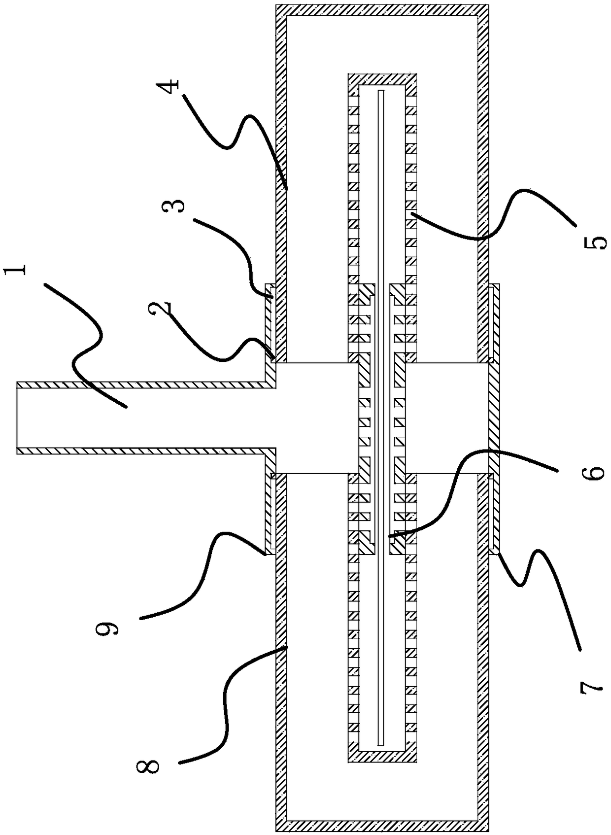
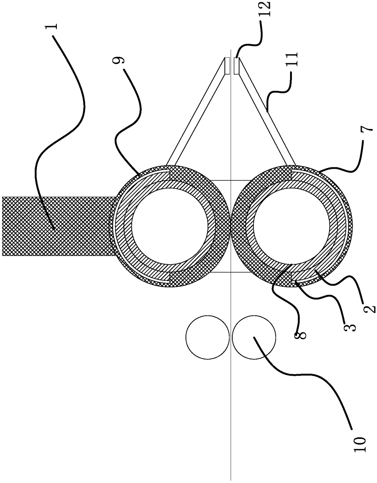
[0016] Such as Figure 1-2 Shown, the technical scheme of the present invention is the die head of a kind of effect coating machine, and it comprises feeding channel 1, the first middle pipe 9, the second middle pipe 7, the first concave pipe 8 that the section is circular and The second concave pipe 4 is characterized in that the sections of the first intermediate pipe 9 and the second intermediate pipe 7 are circular and arranged symmetrically up and down, and the two ends of the first concave pipe 8 are inserted into the first intermediate pipe 9 and one end of the second intermediate pipe 7, the second concave pipe 4 two ends are inserted into the first intermediate pipe 9 and the other end of the second intermediate pipe 7, the first concave pipe 8 and the second concave pipe 4 can be in the first middle Pipeline 9, the second middle pipe 7 lateral movement, the first middle pipe 9, the second middle pipe 7, the first concave pipe 8 and the second concave pipe 4 form a sq...
PUM
 Abstract
Description
Claims
Application Information