Downhole pump unit and downhole drainage test system

A pump unit and drainage pipe technology, which is applied to wellbore/well components, production fluids, earth-moving drilling, etc., can solve the problems that the pump core cannot achieve downhole shut-in, unfavorable thermal recovery of heavy oil, and lack of testing functions. , to achieve the effect of less processing difficulty, lower production cost and larger displacement

Pending Publication Date: 2018-09-28
廊坊市华海石油技术开发有限公司
View PDF0 Cites 7 Cited by
  • Summary
  • Abstract
  • Description
  • Claims
  • Application Information

AI Technical Summary

Problems solved by technology

That is to say, the formation fluid channel is not close to the power fluid channel, which is not conducive to the realization of thermal recovery of heavy oil
[0009] The third is that the pump core itself cannot realize downhole shut-in and does not have the testing function

Method used


Image

  • Downhole pump unit and downhole drainage test system
  • Downhole pump unit and downhole drainage test system
  • Downhole pump unit and downhole drainage test system

Examples


Embodiment Construction

[0050] The application will be further described in detail below in conjunction with the accompanying drawings and embodiments. It should be understood that the specific embodiments described here are only used to explain related inventions, rather than to limit the invention. It should also be noted that, for ease of description, only parts related to the invention are shown in the drawings.

[0051] It should be noted that, in the case of no conflict, the embodiments in the present application and the features in the embodiments can be combined with each other. The present application will be described in detail below with reference to the accompanying drawings and embodiments.

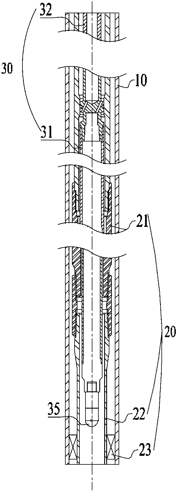
[0052] Please refer to figure 1 It is a structural schematic diagram of an embodiment of a downhole pump unit of the present application, including a working string 20 composed of tubing 22 , a pump seat 21 and a packer 23 that is run into the downhole casing 10 and the running string 20 The drai...


PUM


Abstract

The invention discloses a downhole pump unit and a downhole drainage test system. The downhole pump unit comprises a working pipe string placed down into a downhole casing and a drainage pipe string placed down into the working pipe string, and the working pipe string is composed of an oil pipe, a pump seat and a packer. The packer is located below the pump seat, and the drainage pipe string includes a pump core seated in the pump seat and a hollow sucker rod connected to the top end of the pump core. The technical scheme can separate power fluid from formation fluid, and can realize downholeshut-in and heavy oil heating.

Description

technical field [0001] The present disclosure generally relates to the technical field of oil well testing and testing, and specifically relates to a hydraulically driven, closed-circulation downhole pump unit and a downhole drainage testing system. Background technique [0002] At present, in the field of oil and gas well testing and testing technology, hydraulic pumps or screw pumps are often used for formation drainage, and hydraulic pumps mainly include hydraulic jet pumps and hydraulic piston pumps. [0003] At present, the commonly used hydraulic pumps, whether jet pumps or piston pumps, work by putting the pump core in the working string. The working string should at least consist of tubing, pump base and packer from top to bottom. The pump core is sent to the downhole pump seat through the surface pump, and then the pump pressure is increased to drive the downhole pump to work, and the formation fluid and power fluid are returned from the annular space between the tu...

Claims


Application Information

Patent Timeline
Patent Type & Authority Applications(China)
IPC IPC(8): E21B47/008E21B43/00E21B43/24
CPCE21B43/121E21B43/24E21B47/008
Inventor 赵海库赵雪峰
Owner 廊坊市华海石油技术开发有限公司
Why Eureka
Try Eureka