A leak-proof self-sealing valve

一种自密封、阀门的技术,应用在轴密封、控制阀、阀装置等方向,能够解决不能快速安装和拆卸、不能防外漏等问题

Active Publication Date: 2019-04-30
JIANGSU SUYAN VALVE MASCH CO LTD
View PDF6 Cites 2 Cited by
  • Summary
  • Abstract
  • Description
  • Claims
  • Application Information

AI Technical Summary

Problems solved by technology

[0002] For example, Patent No. CN201720091458.1 is an anti-leakage self-sealing valve, including a valve body, the top of the valve body is provided with a cover, the bottom of the cover is provided with a first groove, and the top of the valve body is provided with There is a second groove, the inside of the first groove is provided with a fixing pin, the inside of the second groove is provided with a fixing hole, and the fixing hole is matched with the fixing pin, and the top of the upper cover is provided with A sealing ring, the middle part of the sealing ring is provided with a vertically downward hollow tube, the inside of the hollow tube is provided with a valve stem, the top of the valve stem is connected with a valve handwheel, and the bottom of the valve handwheel is connected to the The upper cover is fixedly connected; the disadvantage of this utility model is that it cannot be quickly installed and disassembled, and it cannot better prevent leakage by restricting the direction of liquid flow

Method used


Image

  • A leak-proof self-sealing valve
  • A leak-proof self-sealing valve
  • A leak-proof self-sealing valve

Examples


specific Embodiment approach 1

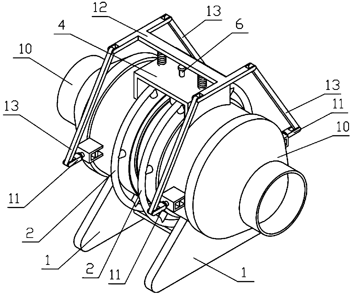
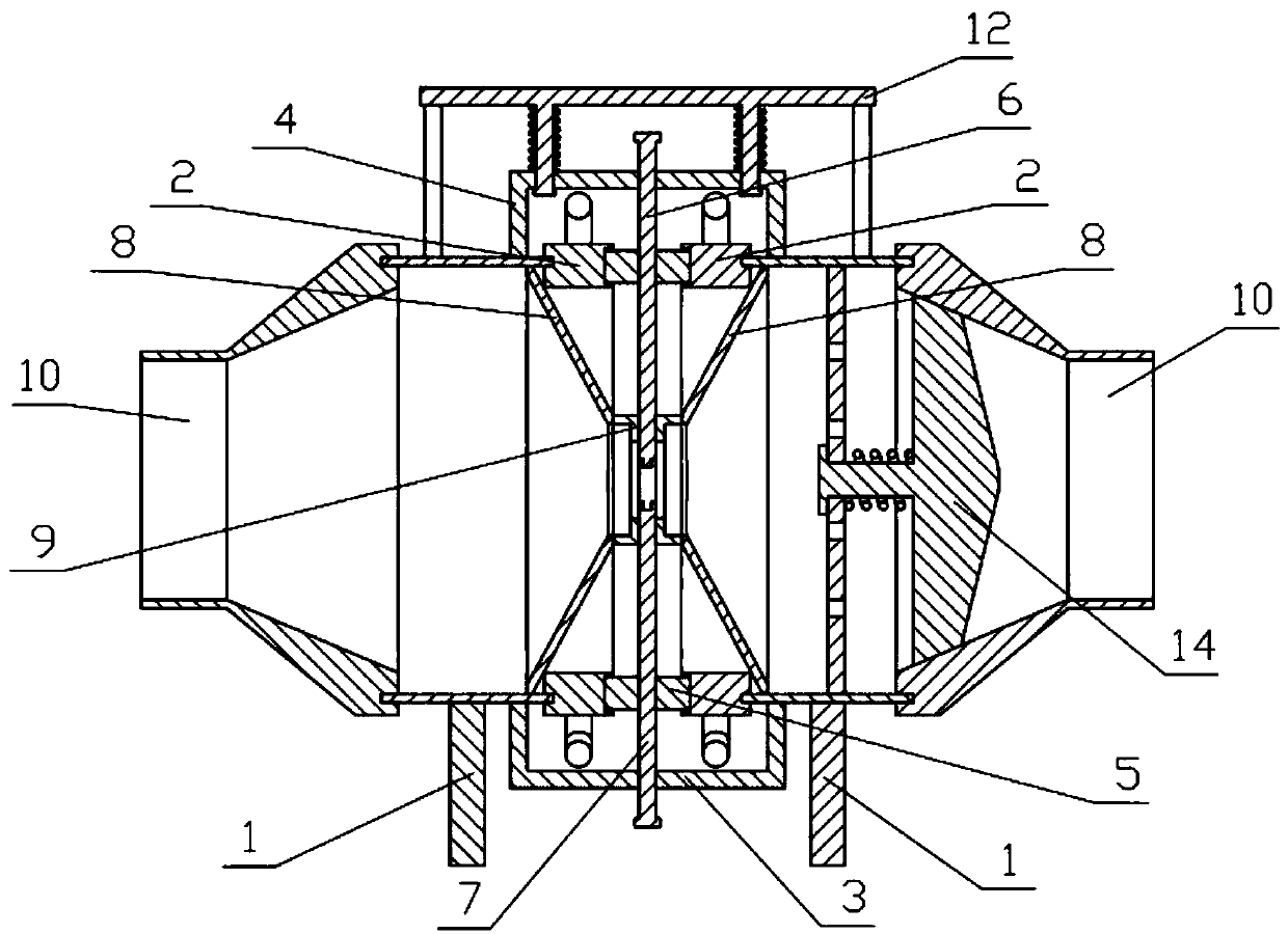
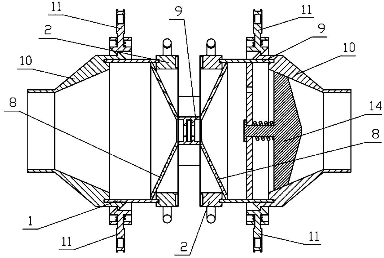
[0039] Combine below Figure 1-18 Describe this embodiment, a leakage-proof self-sealing valve, including a valve bracket 1, a rotating gear 2, a lower connecting plate 3, an upper connecting plate 4, a pinion 5, an upper closing plate 6, a lower closing plate 7, and a conical connection cylinder 8, connecting bracket 9, connecting cylinder 10, clamping mechanism 11, dismounting mechanism 12, connecting rod 13 and one-way mechanism 14, and the valve bracket 1 and the rotating gear 2 are all left and right symmetrically provided with two, two rotating gears 2 Rotate and connect to the inside of the two valve brackets 1 respectively, the left and right ends of the lower connecting plate 3 are respectively fixedly connected to the two valve brackets 1, and the left and right ends of the upper connecting plate 4 are respectively fixedly connected to the two valve brackets 1 , the upper connecting plate 4 is located at the upper end of the lower connecting plate 3, two pinion gears...

specific Embodiment approach 2

[0040] Combine below Figure 1-18 Describe this embodiment, this embodiment will further explain Embodiment 1, the valve bracket 1 includes a valve cylinder 1-1, a valve lower bracket 1-2, a valve side plate I1-3, a valve side plate II1-4 and a circular The through hole Ⅰ1-5, the valve lower bracket 1-2 is fixedly connected to the lower end of the valve cylinder 1-1, four valve side plates Ⅰ1-3 are symmetrically arranged, and the four valve side plates Ⅰ1-3 are respectively fixedly connected to the valve cylinder 1 The front and rear ends of -1, the two valve side plates Ⅰ1-3 at the front and rear ends are fixedly connected with the valve side plate Ⅱ1-4, and the two valve side plates Ⅱ1-4 are provided with circular through holes Ⅰ1-5 .

specific Embodiment approach 3

[0041] Combine below Figure 1-18 Describe this embodiment, this embodiment will further explain the second embodiment, the rotating gear 2 includes a rotating gear body 2-1, a rotating column 2-2, a rotating handle 2-3, a gear groove 2-4 and an installation groove I2 -5, a sealing gasket is arranged in the installation groove I 2-5, and a plurality of rotating columns 2-2 are arranged, and the plurality of rotating columns 2-2 are evenly fixed and connected to the outer side of the rotating gear body 2-1 in the circumferential direction, and the rotating handle 2- 3. It is fixedly connected to the outer sides of a plurality of rotating columns 2-2. The gear groove 2-4 and the installation groove I 2-5 are respectively arranged at the right and left ends of the rotating gear body 2-1. The outer ends of each rotating gear body 2-1 are respectively connected to the inner sides of the two valve cylinders 1-1 through a mounting groove I 2-5; when in use, manually rotate the rotati...


PUM


Abstract

The invention relates to a valve, in particular to an anti-leakage self-sealing valve which comprises a valve support, a rotary gear, a lower connecting plate, an upper connecting plate, a pinion, an upper closing plate, a lower closing plate and a conical connecting cylinder, a connecting support, a connecting cylinder, a clamping mechanism, a disassembling mechanism, a connecting rod and a one-way mechanism.

Description

technical field [0001] The invention relates to a valve, in particular to a leakage-proof self-sealing valve. Background technique [0002] For example, Patent No. CN201720091458.1 is an anti-leakage self-sealing valve, including a valve body, the top of the valve body is provided with a cover, the bottom of the cover is provided with a first groove, and the top of the valve body is provided with There is a second groove, the inside of the first groove is provided with a fixing pin, the inside of the second groove is provided with a fixing hole, and the fixing hole is matched with the fixing pin, and the top of the upper cover is provided with A sealing ring, the middle part of the sealing ring is provided with a vertically downward hollow tube, the inside of the hollow tube is provided with a valve stem, the top of the valve stem is connected with a valve handwheel, and the bottom of the valve handwheel is connected to the The upper cover is fixedly connected; the disadvan...

Claims


Application Information

Patent Timeline
Patent Type & Authority Patents(China)
IPC IPC(8): F16K27/02F16K15/06
CPCF16K15/06F16K27/0209F16K3/029F16K3/30F16K27/044F16K31/53F16K41/04F16K3/0281F16K31/60
Inventor 韩正海韩文豪韩雯文韩昱韩晟
Owner JIANGSU SUYAN VALVE MASCH CO LTD
Why Eureka
Try Eureka