
Coherent laser radar based on pulse coding technology

A technology of pulse coding and laser radar, which is applied in the re-radiation of electromagnetic waves, velocity/acceleration/shock measurement, and the use of re-radiation, etc., which can solve the problems of increasing the aperture of the telescope and increasing the cost

Active Publication Date: 2018-09-28
夏和娣
View PDF21 Cites 19 Cited by
  • Summary
  • Abstract
  • Description
  • Claims
  • Application Information

AI Technical Summary

Problems solved by technology

Taking the method of increasing the aperture of the telescope will greatly increase the cost

Method used


Image

  • Coherent laser radar based on pulse coding technology
  • Coherent laser radar based on pulse coding technology
  • Coherent laser radar based on pulse coding technology

Examples


Embodiment 1

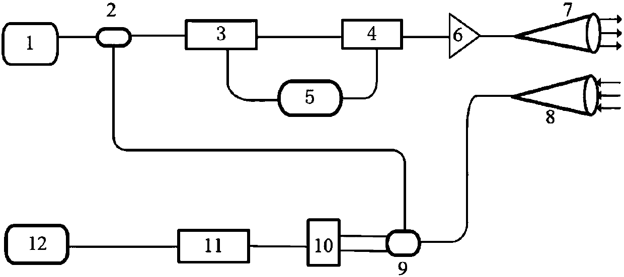
[0053] Such as figure 1 As shown, the present invention provides a coherent lidar based on pulse coding technology, including: a laser 1, a first beam splitter, an electro-optic modulator 3, an acousto-optic modulator 4, a signal generator 5, an amplifier, and an optical transceiver module , coupler, detector 10, acquisition card 11, data processing device; wherein:

[0054] The laser signal output by the laser 1 enters the first beam splitter and is divided into local oscillator light and signal light. The signal light enters the acousto-optic modulator 4 after passing through the electro-optic modulator 3. The signal generator 5 is used to send and the acousto-optic modulator 4 input preset control signals; the electro-optic modulator 3 is used to output the pulse code sequence; the signal output from the acousto-optic modulator 4 enters the optical transceiver module after being amplified by the amplifier, and the optical transceiver module is used for The input signal is ...

Embodiment 2

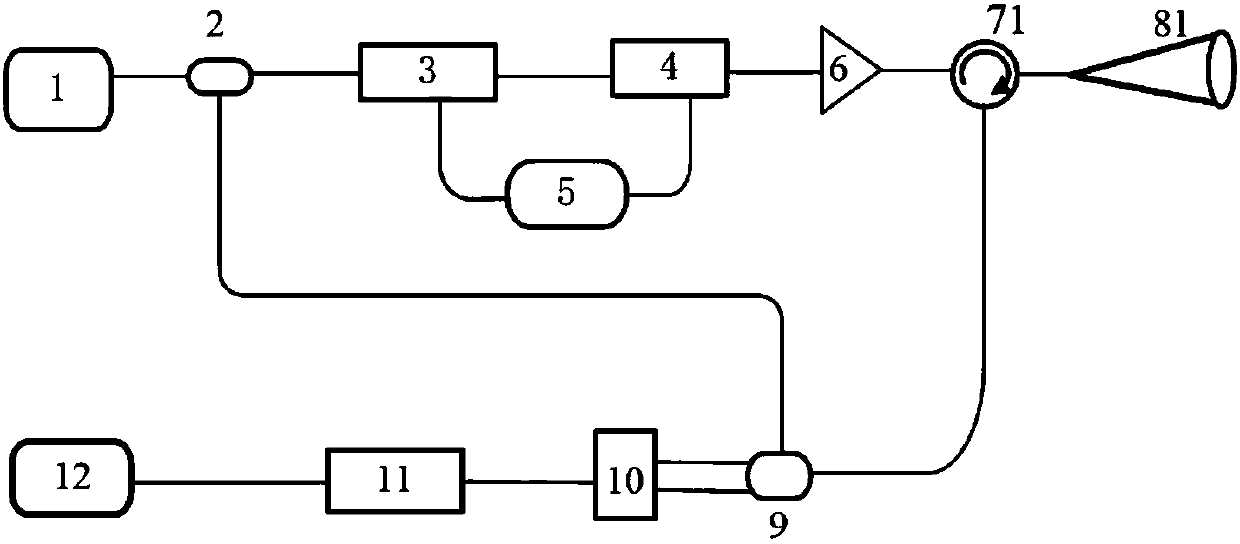
[0102] Such as figure 2 As shown, the present invention provides a coherent lidar based on pulse coding technology, including: a laser 1, a first beam splitter, an electro-optic modulator 3, an acousto-optic modulator 4, a signal generator 5, an amplifier, and an optical transceiver module , coupler, detector 10, acquisition card 11, data processing device; wherein:

[0103] The laser signal output by the laser 1 enters the first beam splitter and is divided into local oscillator light and signal light. The signal light enters the acousto-optic modulator 4 after passing through the electro-optic modulator 3. The signal generator 5 is used to send and the acousto-optic modulator 4 input preset control signals; the electro-optic modulator 3 is used to output the pulse code sequence; the signal output from the acousto-optic modulator 4 enters the optical transceiver module after being amplified by the amplifier, and the optical transceiver module is used for The input signal is...


PUM


Abstract

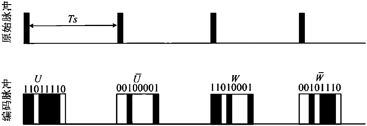
The invention discloses a coherent laser radar based on pulse coding technology. The invention aims at low signal-to-noise ratio (SNR) of echo signals of coherent laser radars, and proposes a method for improving the signal-to-noise ratio of the system and increasing the dynamic range of the system by using the pulse coding technology. The invention outputs the pulse coding sequence codes by an electro-optic modulator, reduces the time-domain cross-correlation between the respective transmit waveforms, reduces auto-correlated side lobes by using the complementary properties of the Golay complementary sequence, and reduces side lobes after the waveform pulse compression. In addition, the present invention performs decoding according to the decoding rule, solves the problem that the pulse peak power of the fiber laser is limited, significantly improves the signal-to-noise ratio of the coherent laser radar, effectively improves the detection range, and does not require pulse accumulationtime, without sacrificing detection time and distance resolution.

Description

technical field [0001] The invention relates to the field of laser radar, in particular to a coherent laser radar based on pulse coding technology. Background technique [0002] Benefiting from high spatial resolution and high measurement accuracy, coherent wind lidar is a hot research field of laser remote sensing. It is particularly worth noting that the 1.5μm-2μm all-fiber coherent wind lidar has the advantages of small size, eye safety, and easy integration, and is an area that countries around the world are vying for development. The international units engaged in pulse coherent lidar research include NASA, NOAA, Lockheed Martin, Raytheon, CTI, Mitsubishi Electric, and Leosphere Company, French Aerospace Research Center (ONERA), British SgurrEnergy Company, British QinetiQ Company, etc. Domestic coherent lidar started relatively late, and the main units include Harbin Institute of Technology, University of Electronic Science and Technology of China, the 27th Research ...

Claims


Application Information

Patent Timeline
Patent Type & Authority Applications(China)
IPC IPC(8): G01S17/58G01S7/484G01P5/26
CPCG01P5/26G01S7/484G01S17/58
Inventor 夏和娣张苏
Owner 夏和娣
Learn More