
1.5μm wavelength aerosol detection lidar and signal decoding method based on pulse coding

A technology of pulse coding and detection of laser light

Active Publication Date: 2022-07-15
UNIV OF SCI & TECH OF CHINA
View PDF6 Cites 0 Cited by
  • Summary
  • Abstract
  • Description
  • Claims
  • Application Information

AI Technical Summary

Problems solved by technology

These can improve the signal-to-noise ratio to a certain extent, but the current pulse power of lasers is limited, increasing the average power of emission by increasing the pulse time domain width will sacrifice the distance resolution; the increase of the telescope aperture will lead to increased cost and reduced stability; However, the pulse accumulation method adopted by the lidar based on the time-of-flight method has the problems of poor time resolution and aliasing distance.

Method used


Image

  • 1.5μm wavelength aerosol detection lidar and signal decoding method based on pulse coding
  • 1.5μm wavelength aerosol detection lidar and signal decoding method based on pulse coding
  • 1.5μm wavelength aerosol detection lidar and signal decoding method based on pulse coding

Examples


Embodiment

[0022] see figure 1 A 1.5μm wavelength aerosol detection laser radar based on pulse coding technology disclosed in the present invention is shown. The purpose of the present invention is to achieve through the following technical solutions, including: a seed laser 1, a first electro-optic modulator 2, a second electro-optic modulator 3, fiber amplifier 4, beam splitter 5, collimator 6, receiving telescope 7, filter 8, indium gallium arsenide quantum detector 9, energy monitoring channel 10, acquisition card 11, computer 12, waveform generator 13; in:

[0023] The output end of the seed laser 1, the first electro-optic modulator 2, the second electro-optic modulator 3, the fiber amplifier 4 and the input end of the beam splitter 5, the output end and the input end of the collimator 6 are sequentially connected; The output end of the receiving telescope 7, the filter 8, the indium gallium arsenide quantum detector 9, the acquisition card 11, the input ends and output ends of th...

specific Embodiment 1

[0048] Specific embodiment 1, for the horizontal detection of aerosols or pollutants, it can effectively improve the radar detection distance, improve the signal-to-noise ratio, and further improve the accuracy of pollutant traceability.

specific Embodiment 2

[0049] The specific embodiment 2 is used for vertical detection of aerosols or clouds, which can improve the radar detection height, improve the signal-to-noise ratio, and improve the cloud penetration ability.

[0050] The 1.5 μm aerosol detection lidar based on the pulse coding technology provided by the embodiment of the present invention has the following beneficial effects:

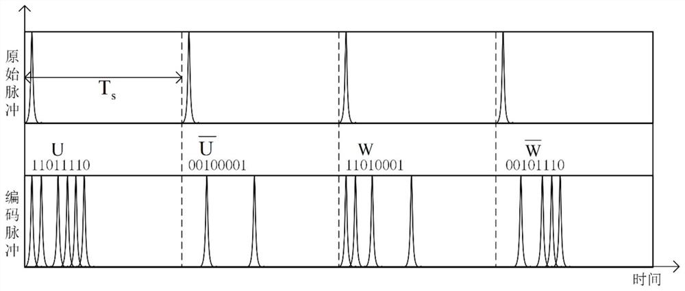
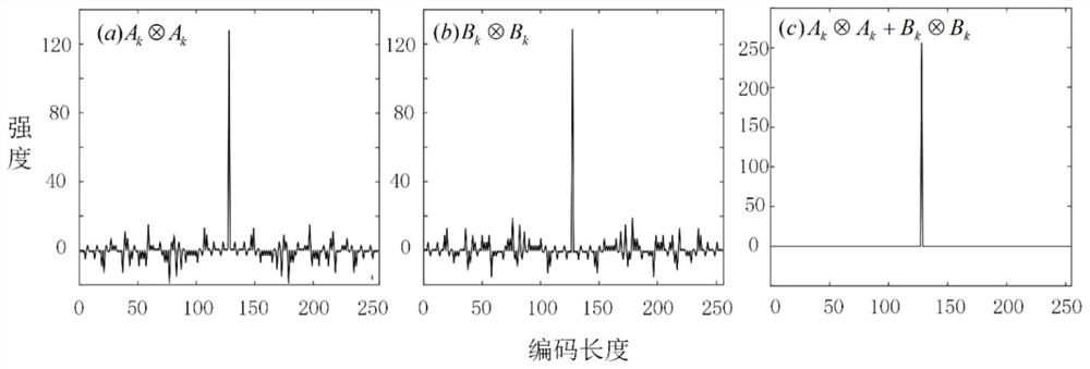
[0051] 1) The pulse train composed of the Golay complementary sequence is pulse encoded to reduce the time-domain cross-correlation between the transmitted waveforms, and the complementary nature of the Golay complementary sequence is used to reduce the side lobes of the autocorrelation and reduce the side lobes after the waveform pulse is compressed.

[0052] 2) Using the Golay coded pulse as the detection pulse of the lidar solves the problem of limited peak power of the fiber laser pulse, significantly improves the signal-to-noise ratio of the lidar, effectively improves the detection distance, and...


PUM


Abstract

The present invention is based on a pulse-coded 1.5 μm wavelength aerosol detection laser radar and a signal decoding method. The laser radar of the present invention includes a seed laser output end, a first electro-optical modulator, a second electro-optical modulator, a fiber amplifier and a beam splitter. The input end, the output end and the input end of the collimator are connected in sequence; the output end of the receiving telescope, the filter, the indium gallium arsenide quantum detector, the acquisition card, each input end of the computer, the output end and the input end of the waveform generator are sequentially connected The input end of the energy detection channel is connected to the output end of the beam splitter, the output end of the energy detection channel is connected to the input end of the acquisition card, and the output end of the waveform generator is respectively connected to the first electro-optical modulator and the second electro-optical modulator. The laser radar and the method of the invention break through the fuzzy distance of the time-of-flight method, improve the stability of the radar system while reducing the volume, improve the ability to identify the distribution of aerosols with large particle size, improve the cloud layer penetration ability, and provide detection equipment for the study of atmospheric science.

Description

technical field [0001] The invention belongs to the technical field of laser radar, and in particular relates to a 1.5 μm wavelength aerosol detection laser radar and a signal decoding method based on pulse coding technology. Background technique [0002] With the increasingly serious environmental pollution, the detection of meteorological elements and pollutants becomes more and more important. Thanks to its high temporal and spatial resolution, lidar is of great benefit in the detection of wind direction, wind speed and pollutant transport. Coherent detection lidar is mainly used to detect atmospheric parameters in the boundary layer, and direct detection lidar can cover the detection of atmospheric parameters at longer distances and at higher altitudes. The Haute-Provence Observatory (OHP) in France has achieved wind detection up to 50 kilometers for the first time using a double-edge FPI as a frequency discriminator, and a single-FPI-based Rayleigh lidar has been devel...

Claims


Application Information

Patent Timeline
Patent Type & Authority Patents(China)
IPC IPC(8): G01S17/95G01S7/493G01S7/487G01S7/481
CPCG01S17/95G01S7/4811G01S7/4876G01S7/493Y02A90/10
Inventor 王冲李文豪王雨薛向辉
Owner UNIV OF SCI & TECH OF CHINA
Learn More