Full-automatic implanting guide plate production method

A production method and fully automatic technology, applied in 3D image processing, image data processing, instruments, etc., can solve the problems of poor comfort of the guide plate, insufficient smoothness of the edge of the guide plate, and reduced overall grid resolution, etc., to achieve enhanced comfort , Improve the generation efficiency, and the effect of fast groove processing operation

Active Publication Date: 2018-09-28
重庆市劢齐医疗科技有限责任公司
View PDF9 Cites 0 Cited by
  • Summary
  • Abstract
  • Description
  • Claims
  • Application Information

AI Technical Summary

Problems solved by technology

[0012] Disadvantages: The idea of ​​combining CBCT and scanning data to generate a planting guide plate is mainly proposed. The design of the guide plate is designed using ready-made design software, and the completed planting guide plate is not proposed.
[0015] Defects: The surface groove processing method based on voxel and spatial implicit function processing is proposed in this paper, which may easily reduce the overall grid resolution after groove processing, and at the same time, the computational complexity of voxel processing is high and the speed is slow
[0016] Summary of the above defects: the current implant guide plate generation technology lacks reliable surface groove processing technology and the automatic adjustment function of the guide hole gap. The edge of the resulting guide bar is not smooth enough, and the guide bar is less comfortable

Method used


Image

  • Full-automatic implanting guide plate production method
  • Full-automatic implanting guide plate production method
  • Full-automatic implanting guide plate production method

Examples


Embodiment Construction

[0046] The preferred embodiments of the present invention will be described in detail below in conjunction with the accompanying drawings, so that the advantages and features of the present invention can be more easily understood by those skilled in the art, so as to define the protection scope of the present invention more clearly.

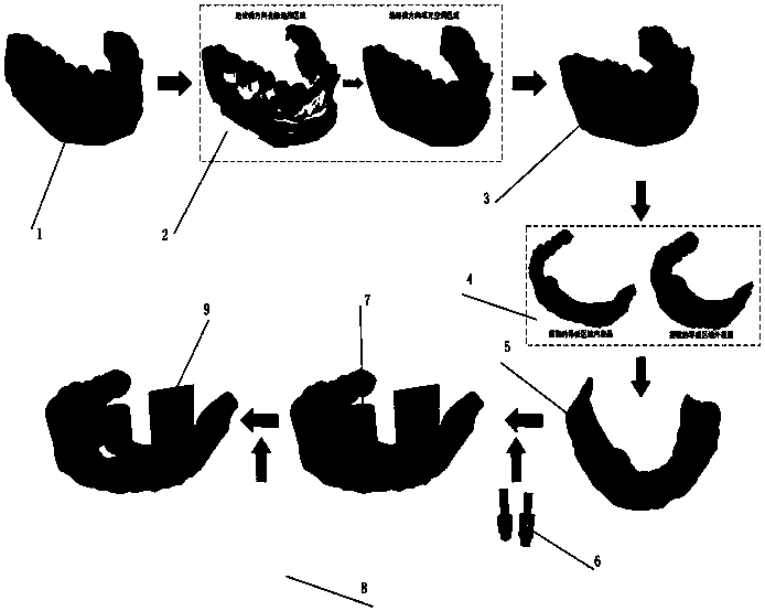
[0047] Such as Figure 1 to Figure 8 Shown: a fully automatic planting guide plate production method,

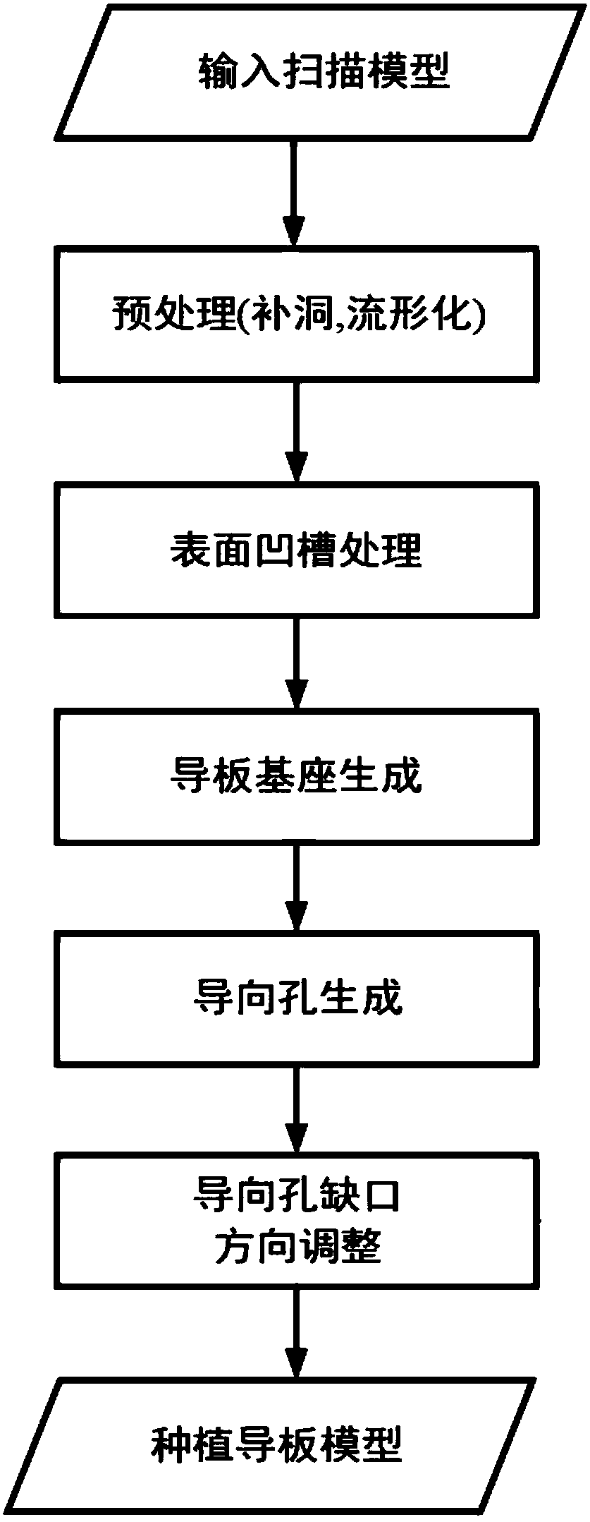
[0048] Take the following steps,

[0049] Step 1: Read the posture information of the oral scan model, dental arch curve, implant and retainer nails aligned with the CBCT image data, and set the guide plate selection boundary. The oral scan model is generally in stl format;

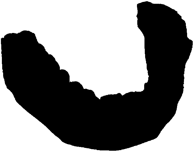
[0050] Step 2: Perform grid hole filling and manifold preprocessing on the oral scan model to obtain the following: figure 2 The preprocessed grid data graph shown in 1;

[0051] Step 3: Calculate the drafting direction of the scanned model. By choosing an appropriate ...


PUM


Abstract

The invention discloses a full-automatic implanting guide plate production method. The method is characterized by comprising the steps that 1, pose information of an oral cavity scanning model, a dental arch curve, an implant and retention pins aligned with CBCT image data is read, and a guide plate selection boundary is set; 2, grid hole filling and manifold preprocessing are performed on the oral cavity scanning model; 3, groove processing is performed on the surface of the scanning model; and 4, the inner surface of an oral cavity scanning model grid is expanded by a certain quantity, an inner layer and an outer layer of a guide plate base are formed, corresponding guide plate regions on the inner layer and the outer layer are selected respectively through the set guide plate selectionboundary, the inner layer and the outer layer are spliced, and meanwhile a gap formed between the inner layer and the outer layer is automatically filled up. Through the method, a guide plate can be generated quickly and efficiently; and after a user inputs required information, the whole process is full-automatic, and therefore guide plate generation efficiency can be substantially improved.

Description

technical field [0001] The invention relates to the field, in particular to a fully automatic method for producing a planting guide plate. Background technique [0002] Defect analysis of this technology in related products: [0003] Related dental implant software products involving implant guide generation: [0004] [0005] [0006] Defect summary: [0007] The current products have deficiencies in the smoothing of the edge of the guide plate and the processing of the grooves of the scanning grid, and most of the current guide plate design products do not have guide hole gaps, resulting in the need for a larger mouth opening for the patient during surgery, which increases the surgical cost. Uncomfortable, very few design software has the function of generating guide hole gaps, but it is necessary to manually adjust the direction of the guide hole gaps. [0008] Brief analysis of defects in related technologies (patents or papers): [0009] Patent name: A digital...

Claims


Application Information

Patent Timeline
Patent Type & Authority Applications(China)
IPC IPC(8): G06T7/00G06T15/00
CPCG06T7/0012G06T15/005G06T2207/30036G06T2207/10081
Inventor 隋伟余泽云
Owner 重庆市劢齐医疗科技有限责任公司
Why Eureka
Try Eureka