Novel structural cable and manufacturing method thereof

A technology of a new structure and manufacturing method, which is applied in the direction of cable/conductor manufacturing, insulating cables, insulating conductors/cables, etc., can solve the problem of large influence of cable current output, and achieve the effect of improving heat dissipation efficiency

Inactive Publication Date: 2018-09-28
ANHUI CABLE
View PDF5 Cites 3 Cited by
  • Summary
  • Abstract
  • Description
  • Claims
  • Application Information

AI Technical Summary

Problems solved by technology

[0003] Moreover, the existing external environment has a great influence on the current output of the cable, especially in a lightning environment, it is easy to make the voltage passing through the cable become a peak voltage

Method used


Image

  • Novel structural cable and manufacturing method thereof
  • Novel structural cable and manufacturing method thereof
  • Novel structural cable and manufacturing method thereof

Examples


Embodiment 1

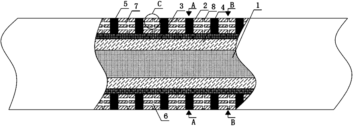
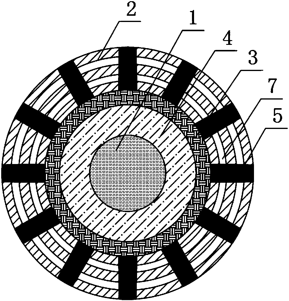
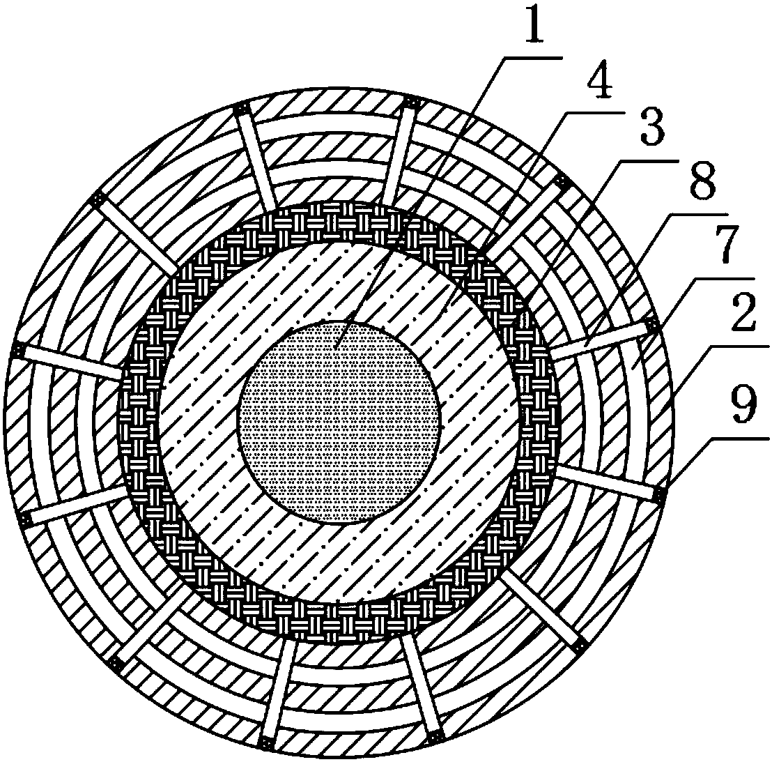
[0028] according to Figure 1-4 A new type of structural cable is shown, including a conductor 1 and an insulating layer 2, the insulating layer 2 is arranged around the outer wall of the conductor 1, and the inner wall of the insulating layer 2 is fixed and surrounded by a sealing layer 3, through which the sealing layer 3 The setting can not only make the filling layer 4 achieve a sealed environment, prevent the inert gas in the filling layer 4 from overflowing, but also conduct heat conduction to the heat emitted by the conductor 1, and at the same time, it can also achieve the effect of passing the current through the conductor 1. The effect of insulation, the filling layer 4 is arranged between the sealing layer 3 and the conductor 1, through the setting of the filling layer 4, the stability of the inert gas is used to avoid the direct contact of the sealing layer 3 with the conductor 1, and the sealing layer 3 is avoided. The aging phenomenon occurs under the electric fi...

Embodiment 2

[0031] The present invention also provides a manufacturing method of a novel structural cable, the specific operation steps of which are as follows:

[0032] Step 1: Material preparation: Prepare sufficient materials, extruders and grinders for cable manufacturing in advance;

[0033] Step 2: Extrusion: First, uniformly extrude the sealing layer 3 on the outer wall side of the conductor 1, so that the thickness of the extruded sealing layer 3 is set between 1 mm and 3 mm, and leave a gap between the conductor 1 and the sealing layer 3. There is a distance of 4mm~6mm, and one end of the filling layer 4 is sealed, and the other end is not sealed first, and then the thermal conduction column 5 is fixed on the outer wall side of the sealing layer 3 by an adhesive, and then the sealing layer 3 is sealed by an extruder. The insulating layer 2 is uniformly extruded around one side of the outer wall, and when the insulating layer 2 is extruded, the heat exchanging hole 6 is used to le...


PUM

PropertyMeasurementUnit
thicknessaaaaaaaaaa
diameteraaaaaaaaaa

Abstract

The invention discloses a novel structural cable and a manufacturing method thereof, comprising a conductor and an insulating layer, wherein the insulating layer is disposed around one side of the outer wall of the conductor, a sealing layer is fixedly disposed around the inner wall of the insulating layer, a filling layer is disposed between the sealing layer and the conductor, a heat-conductingcolumn is disposed on one side of the outer wall of the sealing layer, one end of the heat-conducting column is inserted through the insulating layer and extends to one side of the outer wall of the insulating layer, and the heat-conducting column is provided with a heat exchange hole. The invention avoids the direct contact of the sealing layer with the conductor, and avoids the aging phenomenonof the sealing layer under the electric field generated by the conductor for a long time by setting the filling layer and utilizing the stability of the inert gas, thereby shortening the service lifeof the cable and increasing the danger of the cable to the outside world, and avoids the peak voltage generated nearby to affect the voltage output of the cable, for example, lightning will convert the voltage flowing through the conductor into a peak voltage, by using the filled inert gas, thereby generating damages to equipment.

Description

technical field [0001] The invention relates to the technical field of electric power and cables, in particular to a novel structural cable and a manufacturing method thereof. Background technique [0002] As an important pillar industry of the national economy, wire and cable accounts for an increasing proportion of the national economy. As a relatively mature industry, the cost reduction of wire and cable is also more and more valued by the industry. The cable structure is more divided into two levels, and the first level is highly integrated and complicated. It integrates multiple functions into one, saving laying, Operation and maintenance costs; the other level is structural simplification. In the case of meeting industry standards, national standards, and enterprise standards, the structure should be as simple as possible and the cost as low as possible. This method meets the requirements of a low-carbon environment. [0003] Moreover, the existing external environmen...

Claims


Application Information

Patent Timeline
Patent Type & Authority Applications(China)
IPC IPC(8): H01B7/02H01B7/28H01B7/42H01B13/14H01B13/22H01B13/24
CPCH01B7/02H01B7/28H01B7/428H01B13/14H01B13/221H01B13/24Y02A30/14
Inventor 张万有周俊夏候东韩俊宝高从民徐晓丽朱元忠陈安鹏
Owner ANHUI CABLE
Why Eureka
Try Eureka