E-band high-performance antenna

A high-performance, antenna technology, applied in the direction of antenna, antenna grounding switch structure connection, radiation element structure, etc., can solve the problems of unstable and mature process, complex amplitude and phase balance design, large dielectric loss, etc., to ensure electrical performance , simple structure and low cost

Pending Publication Date: 2018-09-28
TONGYU COMM INC
View PDF4 Cites 2 Cited by
  • Summary
  • Abstract
  • Description
  • Claims
  • Application Information

AI Technical Summary

Problems solved by technology

The planar array antenna is made in the form of SIW or waveguide slot array, the radiation unit is small, and the antenna profile is greatly reduced. Low; the traditional waveguide slot array adopts the form of series feed, its amplitude and phase balance design is relatively complicated, and the process is not stable enough mature and stable

Method used


Image

  • E-band high-performance antenna
  • E-band high-performance antenna
  • E-band high-performance antenna

Examples


Embodiment Construction

[0025] The following will clearly and completely describe the technical solutions in the embodiments of the present invention with reference to the accompanying drawings in the embodiments of the present invention. Obviously, the described embodiments are only some, not all, embodiments of the present invention. Based on the embodiments of the present invention, all other embodiments obtained by persons of ordinary skill in the art without making creative efforts belong to the protection scope of the present invention.

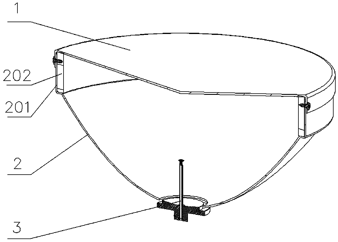
[0026] Such as figure 1 As shown, an E-band high-performance antenna of the present invention includes a reflector 2 with a parabolic structure, a radome 1 fixed on the large end of the reflector 2 and a feed 3 fixed on the small end of the reflector 2 . The reflective surface 2 utilizes the radiation characteristics of the paraboloid itself to gather energy and transmit directional radiation. As the main radiation medium of electromagnetic wave energy, in add...


PUM


Abstract

The invention relates to the technical field of a microwave antenna, and specifically relates to an E-band high-performance antenna, comprising a reflective surface, an antenna cover and a feed source; the feed source comprises a feed source base, a waveguide tube, radiation dielectric and a secondary reflective surface; a through hole is formed in the central position of the feed source base; a waveguide port is formed in one, positioned on the exterior of the reflective surface, of the through hole, and the waveguide tube is inserted in one end positioned in the inner cavity of the reflective surface; the radiation dielectric adopts a T-shaped structure, and comprises lower part dielectric inserted in the waveguide tube and opposite to one end of the feed source base, and upper part dielectric arranged on the exterior of the waveguide tube; an annular groove is formed in the outer edge of the lower part dielectric; at least one layer of annular stage is arranged on the outer edge ofthe upper part dielectric; a conical groove is formed in the end plane, opposite to the lower part dielectric, of the upper part dielectric; and the secondary reflective surface is matched with the conical groove in shapes and attached in the conical groove. The E-band high-performance antenna is simple and convenient to mount, easy to produce, low in cost, low in dielectric loss and high in frequency band.

Description

technical field [0001] The invention relates to the technical field of microwave antennas, in particular to an E-band high-performance antenna. Background technique [0002] Microwave is the most commonly used wireless communication technology at present. It has long transmission distance, large capacity, fast deployment and strong stability. It is now widely used in the relay and backhaul of various communication systems. At present, conventional 6GHz-38GHz microwave spectrum resources have been rapidly exhausted, and E-band (71GHz-86GHz) microwave frequency band will be an important means of wireless transmission. In order to pursue the characteristics of miniaturization and easy integration, E-band flat panel technology is being extensively studied. The planar array antenna is made in the form of SIW or waveguide slot array, the radiation unit is small, and the antenna profile is greatly reduced. Low; the traditional waveguide slot array adopts the form of series feed, ...

Claims


Application Information

Patent Timeline
Patent Type & Authority Applications(China)
IPC IPC(8): H01Q1/36H01Q1/42H01Q1/50H01Q19/12
CPCH01Q1/36H01Q1/42H01Q1/50H01Q19/12
Inventor 李骁男陈鹏羽张锐明李健林熊国辉刘彬彬林泽银
Owner TONGYU COMM INC
Why Eureka
Try Eureka