Electric connector

A technology for electrical connectors and connecting parts, applied in the direction of connection, fixed connection, circuit, etc., can solve the problems of reducing assembly efficiency, large size, and increasing the production cost of high-current connectors, so as to improve market competitiveness and reduce production costs. , the effect of reducing the volume

Active Publication Date: 2018-09-28
DEYI PRECISION ELECTRONIC IND CO LTD PANYU
View PDF5 Cites 4 Cited by
  • Summary
  • Abstract
  • Description
  • Claims
  • Application Information

AI Technical Summary

Problems solved by technology

However, in this high-current connector, the accommodation space of the housing part needs to accommodate the two terminals and the clamping part at the same time, which is not conducive to the miniaturization design of the housing part, and thus causes the entire large current The structure of the connector product is complex and the volume is too large, which does not conform to the current trend of miniaturization of electronic products; in addition, the clamping part clamps the two terminals at the same time, which also increases the difficulty of assembling the high-current connector and reduces the improve its assembly efficiency and increase the production cost of the high-current connector

Method used


Image

  • Electric connector
  • Electric connector
  • Electric connector

Examples


Embodiment Construction

[0029] In order to facilitate a better understanding of the purpose, structure, features, and effects of the present invention, the present invention will now be further described in conjunction with the accompanying drawings and specific embodiments.

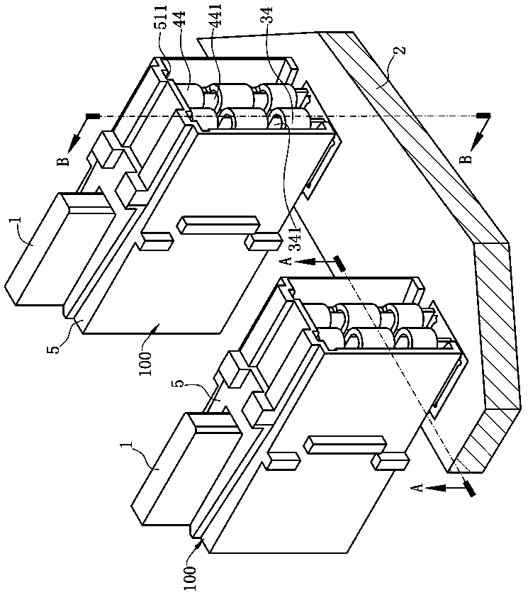
[0030] Such as figure 1 As shown, the electrical connector 100 of the present invention is a vertical high-current electrical connector 100 for connecting an electronic card 1 to a circuit board 2, and each of the electrical connectors 100 is for one electronic card 1 to be plugged into. A plurality of electrical connectors 100 are arranged in a row on the same circuit board 2 for insertion of a plurality of parallel electronic cards 1 .

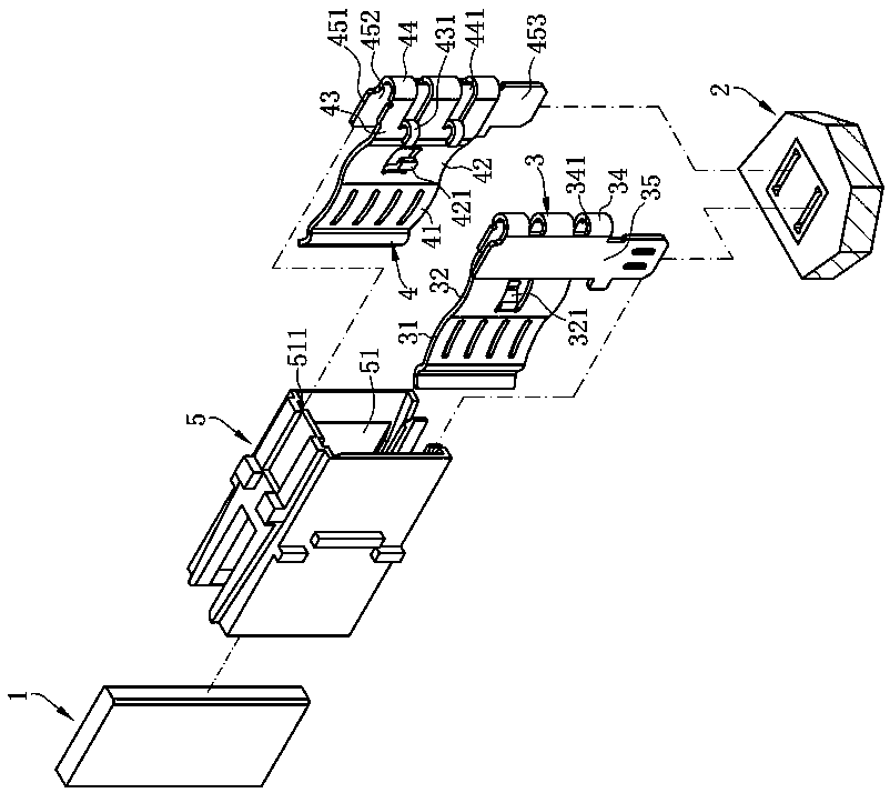
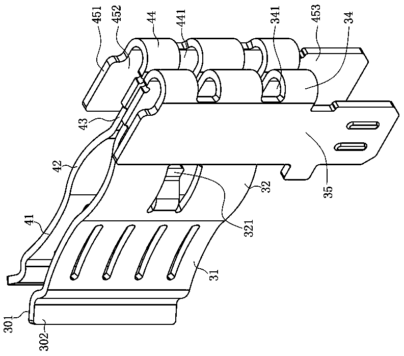
[0031] Such as figure 2 As shown, the electrical connector 100 includes an insulating body 5, a first terminal 3 and a second terminal 4 are accommodated in the insulating body 5, and one end of the first terminal 3 and the second terminal 4 are clamped together. The electronic card 1 is h...


PUM


Abstract

The invention discloses an electric connector in conduction connection with an electronic card and a circuit board. The electric connector comprises an insulation body, a front end of the insulation body is recessed backwards to form the accommodation space, a first terminal is accommodated in the accommodation space, a second terminal is arranged opposite to the first terminal and is accommodatedin the accommodation space, the second terminal comprises a contact portion abutting the opposite other side of the electronic card, a conduction connection portion arranged at the back of the contact portion, a first elastic portion connected with the contact portion, a second elastic portion connected with the conduction connection portion, and a connection portion connected with the first elastic portion and the second elastic portion, the conduction connection portion is in conduction connection with a circuit board, the connection portion is provided with a pull-holding member, and the first terminal is held by the pull-holding member. The first terminal is held by the pull-holding member, so mutual separation of the first terminal and the second terminal is avoided, the first terminal and the second terminal can be further made to simultaneously swing or move, the structure is simple, assembling is easy, and production cost is reduced.

Description

technical field [0001] The invention relates to an electrical connector, especially an electrical connector for large current transmission. Background technique [0002] Chinese patent CN201620293845.9 discloses a high-current connector, which includes a housing part, a power terminal group part accommodated in the housing part, and a U-shaped clamping part that clamps the power terminal group part, The power supply terminal part includes two opposite terminals, and the clamping part clamps the two terminals, so that the two terminals can swing or move synchronously, ensuring that when the docking connector is inserted, the two terminals The terminal can be stably electrically connected to the docking connector at the same time, improving the stability and safety of the current transmission of the high-current connector. However, in this high-current connector, the accommodation space of the housing part needs to accommodate the two terminals and the clamping part at the sa...

Claims


Application Information

Patent Timeline
Patent Type & Authority Applications(China)
IPC IPC(8): H01R12/70H01R12/50H01R13/02
CPCH01R12/50H01R12/70H01R13/02
Inventor 张文昌
Owner DEYI PRECISION ELECTRONIC IND CO LTD PANYU
Why Eureka
Try Eureka