Lightning arrester

A lightning rod and transmission cavity technology, applied in the field of lightning rods, can solve the problems of single function of lightning rods, waste of resources and manpower, etc., and achieve the effect of ingenious structure and precise design

Inactive Publication Date: 2018-09-28
项浩定
View PDF3 Cites 1 Cited by
  • Summary
  • Abstract
  • Description
  • Claims
  • Application Information

AI Technical Summary

Problems solved by technology

[0002] The traditional lightning rod has a single function and a simple structure. When a building needs multiple functions, it is necessary to install a variety of equipment on the top of the building, which is a waste of resources and manpower. The functions of the top are integrated together, and certain treatment and protection are carried out for the rainwater falling

Method used


Image

  • Lightning arrester
  • Lightning arrester
  • Lightning arrester

Examples


Embodiment Construction

[0015] All features disclosed in this specification, or steps in all methods or processes disclosed, may be combined in any manner, except for mutually exclusive features and / or steps.

[0016] Any feature disclosed in this specification (including any appended claims, abstract and drawings), unless expressly stated otherwise, may be replaced by alternative features which are equivalent or serve a similar purpose. That is, unless expressly stated otherwise, each feature is one example only of a series of equivalent or similar features.

[0017] The present invention will be described in detail below in conjunction with the drawings.

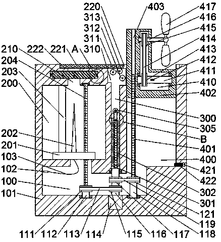
[0018] refer to Figure 1-Figure 3 As shown, a lightning rod of the present invention includes a device casing 101, and a first transmission chamber 100 is arranged inside the device casing 101, and a first rotating shaft 112 is mounted on the inner bottom wall of the first transmission chamber 100 for rotation. The outer surface of the first r...


PUM


Abstract

The invention discloses a lightning arrester. The lightning arrester comprises a device casing, a first transmission cavity is formed in the device casing, a first rotating shaft is rotatably and cooperatively mounted on the inner bottom wall of the first transmission cavity, a first belt pulley is fixedly arranged on the outer surface of the first rotating shaft, a first threaded rod is fixedly arranged at the upper end of the first rotating shaft, a first motor is disposed in the inner bottom wall of the first transmission cavity, and a second rotating shaft is in power connection with the upper end of the first motor. A second belt pulley is fixedly arranged on the outer surface of the second rotating shaft, a first belt is cooperatively in transmission connection between the second belt pulley and the first belt pulley, a third belt pulley is fixedly arranged on the outer surface of the second rotating shaft, a second threaded rod is fixedly arranged at the upper end of the secondrotating shaft, and a third rotating shaft is rotatably and cooperatively mounted on the inner bottom wall of the first transmission cavity. A fourth belt pulley is fixedly arranged on the outer surface of the third rotating shaft, and a second belt is cooperatively in transmission connection between the fourth belt pulley and the third belt pulley.

Description

technical field [0001] The invention relates to the field of architectural design, in particular to a lightning rod. Background technique [0002] The traditional lightning rod has a single function and a simple structure. When a building needs multiple functions, it is necessary to install a variety of equipment on the top of the building, which is a waste of resources and manpower. Therefore, there is an urgent need for a compact and precisely designed device. The functions of the top are integrated together, and certain treatment and protection are carried out for the rainwater falling. Contents of the invention [0003] The object of the present invention is to provide a lightning rod that can overcome the above-mentioned defects of the prior art. [0004] According to the present invention, a lightning rod of the present invention includes a device casing, a first transmission cavity is arranged inside the device casing, and a first rotating shaft is mounted on the b...

Claims


Application Information

Patent Timeline
IPC IPC(8): H01T19/04G01P5/00
CPCH01T19/04G01P5/00
Inventor 余芳珺
Owner 项浩定
Why Eureka
Try Eureka