Combined-type wiring groove and combined-type table
A wiring trough and splicing technology, which is applied to tables, tables with variable table heights, legs of general furniture, etc., can solve problems such as burden, increased cost, and inability to meet the supporting use of tabletops, and achieve small operating space and high production efficiency. The effect of cost reduction, convenient and rich production
- Summary
- Abstract
- Description
- Claims
- Application Information
AI Technical Summary
Problems solved by technology
Method used
Image
Examples
Embodiment 1
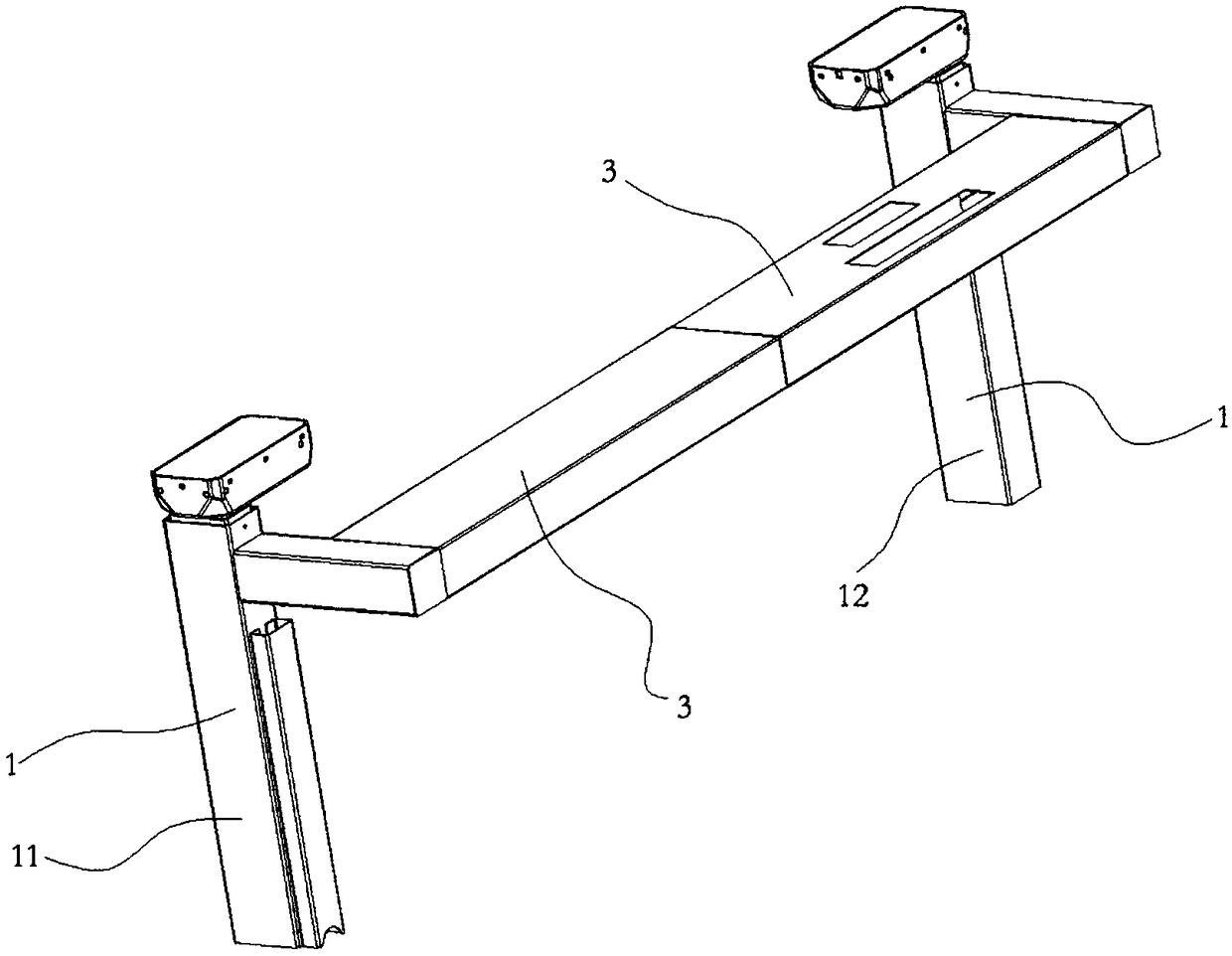
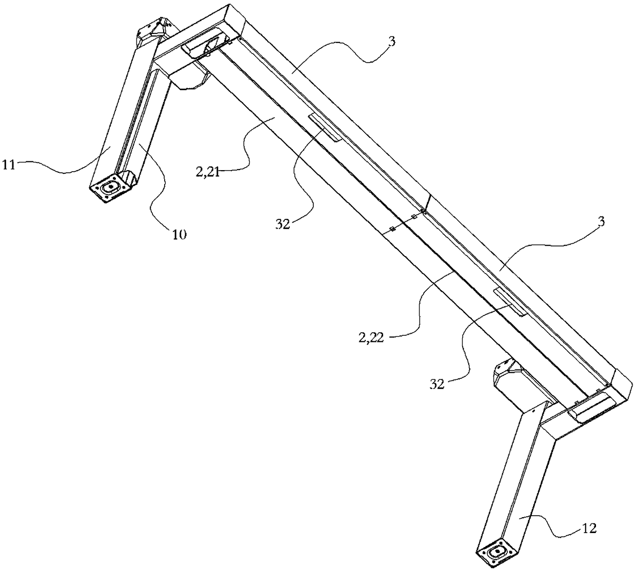
[0032] see Figure 1-2 .
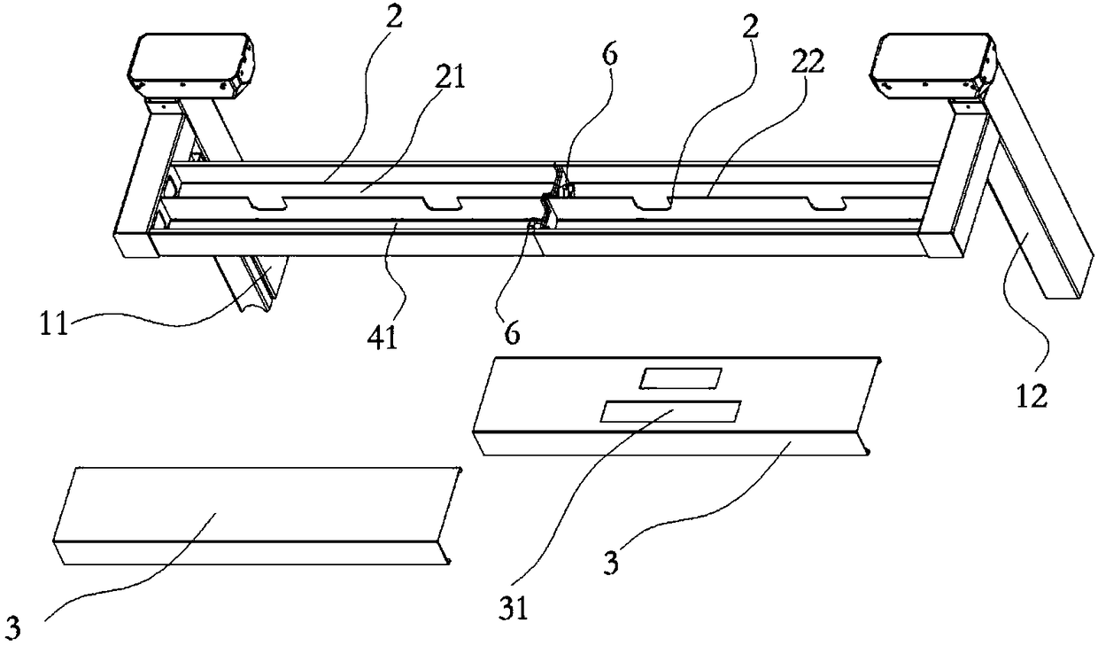
[0033] This embodiment provides a spliced wiring trough, which includes a wiring trough, and the wiring trough is installed on a column 1 , or installed between adjacent columns 1 . Wherein, the wiring trough includes more than two single wiring troughs 2 , and all the single wiring troughs 2 are fixed and spliced with each other and installed between adjacent columns 1 . This structure avoids the installation method of connecting different uprights 1 directly by using long-length wire troughs in the prior art. The body groove 2 is spliced, and then different columns 1 are connected. This connection mode takes the length of the single wiring groove 2 as the unit of change, and can be adapted to different distances between adjacent columns 1 , thereby adapting to the use of larger or smaller size lift tables. Wherein the column 1 of this embodiment is an electric push rod.
[0034] see figure 2 .
[0035] A magnet may be provided at the bot...
Embodiment 2
[0058] see Figure 7 .
[0059] This implementation is exactly the same as the connection mode between the single wiring grooves 2 in the first embodiment. The difference is that the single wiring groove 2 is divided into a long single groove 23 and a short groove 24 , and the length of the long groove 23 is greater than or equal to the length of the short groove 24 . At the same time, the left column 11 and the right column 12 are connected through the left individual groove 21 , the middle individual groove 25 and the right individual groove 22 . Wherein, the left monomer groove 21 for wiring and the right monomer groove 22 for wiring are long grooves 23 for a single wiring, and the single groove 25 for a middle wiring is a short groove 24 for a single wiring.
[0060] The single long groove 23 and the short groove 24 further enrich the specifications of the single groove 2, which can be adapted to tables with more sizes and specifications, especially small-sized tables, w...
Embodiment 3
[0064] see Figure 8 .
[0065]This embodiment is a spliced table, which includes a plurality of table boards 100 , and the bottom of each table board 100 is installed with the spliced cable duct described in Embodiment 1 and Embodiment 2. The single wiring grooves 2 of adjacent table boards 100 are connected to each other, so that the lines of different table boards 100 are connected to each other. This solution maintains a constant relative horizontal position between different tables, which is convenient for streamlined operations on different tables, and can greatly increase the number of people working at the same time.
[0066] For example, in this embodiment, the number of table boards 100 is selected as two, which are respectively a small table board 101 with a length of 1600 mm and a large table board 102 with a length of 1800 mm.
[0067] The bottom of the small table 101 is vertically provided with two columns 1, and the distance between the two columns 1 and ...
PUM
 Abstract
Description
Claims
Application Information
 - R&D
- Intellectual Property
- Life Sciences
- Materials
- Tech Scout
- Unparalleled Data Quality
- Higher Quality Content
- 60% Fewer Hallucinations
Browse by: Latest US Patents, China's latest patents, Technical Efficacy Thesaurus, Application Domain, Technology Topic, Popular Technical Reports.
© 2025 PatSnap. All rights reserved.Legal|Privacy policy|Modern Slavery Act Transparency Statement|Sitemap|About US| Contact US: help@patsnap.com


