
Solar photovoltaic panel snow-cleaning de-icing device

A technology of solar photovoltaic panels and snow shovels, applied in photovoltaic power generation, photovoltaic modules, electrical components, etc., can solve problems that affect power generation efficiency, fail to reach power generation or lighting, and fail to work normally

Inactive Publication Date: 2018-09-28
合肥银创宏达机器人有限公司
View PDF0 Cites 4 Cited by
  • Summary
  • Abstract
  • Description
  • Claims
  • Application Information

AI Technical Summary

Problems solved by technology

The snow on the solar photovoltaic panel in the related art is greatly affected by the season or temperature, so that the solar photovoltaic panel cannot work normally for at least 1 / 4 of the year, and cannot achieve the effect of power generation or lighting
The traditional solar photovoltaic panel snow removal device can only remove the snow on the surface, but not the frozen surface of the solar photovoltaic panel, which often leads to a decrease in the light transmittance of the solar photovoltaic panel and directly affects the power generation efficiency

Method used


Image

  • Solar photovoltaic panel snow-cleaning de-icing device
  • Solar photovoltaic panel snow-cleaning de-icing device

Examples


Embodiment 1

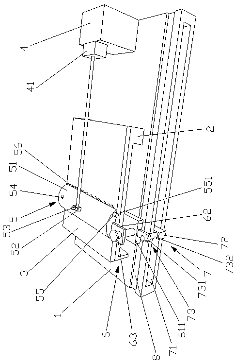
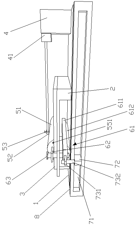
[0019] Such as Figure 1-2 As shown, a solar photovoltaic panel snow removal and deicing device of the present invention includes a solar photovoltaic panel base 1, a solar photovoltaic panel support frame 2 is arranged on the solar photovoltaic panel base 1, and the solar photovoltaic panel support frame 2 is a U-shaped structure. And the U-shaped opening of the solar photovoltaic panel support frame 2 faces the solar photovoltaic panel base 1, the solar photovoltaic panel support frame 2 is provided with a solar photovoltaic panel 3, the solar photovoltaic panel base 1 is also provided with a cylinder seat 4, and the cylinder seat 4 is provided with There is a cylinder 41, a snow removal shovel 5 is movable on the solar photovoltaic panel 3, the piston rod of the cylinder 41 is movably connected with the snow removal shovel 5, and an elastic adjustment device 6 is also arranged in the U-shaped opening of the solar photovoltaic panel support frame 2. 6 includes a rolling base...

Embodiment 2

[0021]The solar photovoltaic panel base 1, the solar photovoltaic panel base 1 is provided with a solar photovoltaic panel support frame 2, the solar photovoltaic panel support frame 2 is a U-shaped structure, and the U-shaped opening of the solar photovoltaic panel support frame 2 faces the solar photovoltaic panel base 1, The solar photovoltaic panel support frame 2 is provided with a solar photovoltaic panel 3, the solar photovoltaic panel base 1 is also provided with a cylinder seat 4, the cylinder seat 4 is provided with a cylinder 41, and the solar photovoltaic panel 3 is provided with a snow removal shovel 5 and a cylinder 41. The piston rod is movably connected with the snow removal shovel 5, and the U-shaped opening of the solar photovoltaic panel support frame 2 is also provided with an elastic adjustment device 6. The elastic adjustment device 6 includes a rolling base 61 and a support plate 62, and the rolling base 61 is movably arranged on the solar photovoltaic pan...


PUM


Abstract

The invention provides a solar photovoltaic panel snow-cleaning de-icing device, and specifically relates to the technical field of the photovoltaic equipment. The solar photovoltaic panel snow-cleaning de-icing device comprises a solar photovoltaic panel base, a solar photovoltaic panel support frame is arranged on the solar photovoltaic panel base, and the solar photovoltaic panel support frameis a U-shaped structure; a solar photovoltaic panel is arranged on the solar photovoltaic panel support frame, a cylinder seat is further arranged on the solar photovoltaic base, a cylinder is arranged on the cylinder seat, and a snow-removing shovel is movably arranged on the solar photovoltaic panel, and a piston rod of the cylinder is movably connected with the snow-removing shovel; and a slackadjusting device is further arranged in the U-shaped opening of the solar photovoltaic panel support frame. The solar photovoltaic panel snow-cleaning de-icing device provided by the invention can remove the snow and ice on the surface of the solar photovoltaic panel; furthermore, the cylinder can drive the snow-removing shovel body to reciprocate through a reinforcement block, thereby playing the guiding effect; the snow-removing shovel is prevented from inclining when shoveling the snow on the solar photovoltaic panel, and the de-icing quality is guaranteed.

Description

technical field [0001] The invention relates to the technical field of photovoltaic equipment, in particular to a snow and ice removal device for solar photovoltaic panels. Background technique [0002] Snow accumulation on solar photovoltaic panels is a huge obstacle to the normal operation of solar energy. Especially in areas with thick snow cover, solar photovoltaic panels cannot receive solar energy due to being covered by snow, so they cannot work normally. The solar photovoltaic panel includes a plurality of photovoltaic modules, and the photovoltaic modules are connected to each other to form a photovoltaic array, and connecting seams are formed between adjacent photovoltaic modules. When in use, the photovoltaic array usually forms a solar power generation device together with an inverter and a battery. The photovoltaic array converts solar energy into electrical energy, and the inverter converts the direct current generated by the photovoltaic array into alternati...

Claims


Application Information

Patent Timeline
Patent Type & Authority Applications(China)
IPC IPC(8): H02S40/12
CPCH02S40/12Y02E10/50
Inventor 余爱玲
Owner 合肥银创宏达机器人有限公司
Learn More