
Heat dissipation cycle structure

A circulation structure and heat dissipation unit technology, which is applied in the construction parts of electrical equipment, cooling/ventilation/heating transformation, electrical components, etc., can solve the problems of gas retention, exhaustion, poor heat dissipation, etc.

Inactive Publication Date: 2018-09-28
ASIA VITAL COMPONENTS SHENZHEN CO LTD
View PDF5 Cites 0 Cited by
  • Summary
  • Abstract
  • Description
  • Claims
  • Application Information

AI Technical Summary

Problems solved by technology

[0004] However, the above-mentioned heat dissipation circulation process is only for heat exchange and heat dissipation inside the chassis (cabinet), where a plurality of heating elements are arranged inside the chassis (cabinet), and the temperature of the gas discharged through the water drain and fan installed inside the chassis (cabinet) It is also relatively high, and because the chassis (cabinet) is a closed space, this will cause hotter gas to stay inside the chassis (cabinet) and cannot be discharged, which will easily cause a vicious circle in which the overall heat dissipation efficiency continues to decline. Lead to extremely poor cooling effect and poor heat exchange efficiency

Method used


Image

  • Heat dissipation cycle structure
  • Heat dissipation cycle structure
  • Heat dissipation cycle structure

Examples


Embodiment Construction

[0032] The above-mentioned purpose of the present invention and its structural and functional characteristics will be described according to the preferred embodiments of the accompanying drawings.

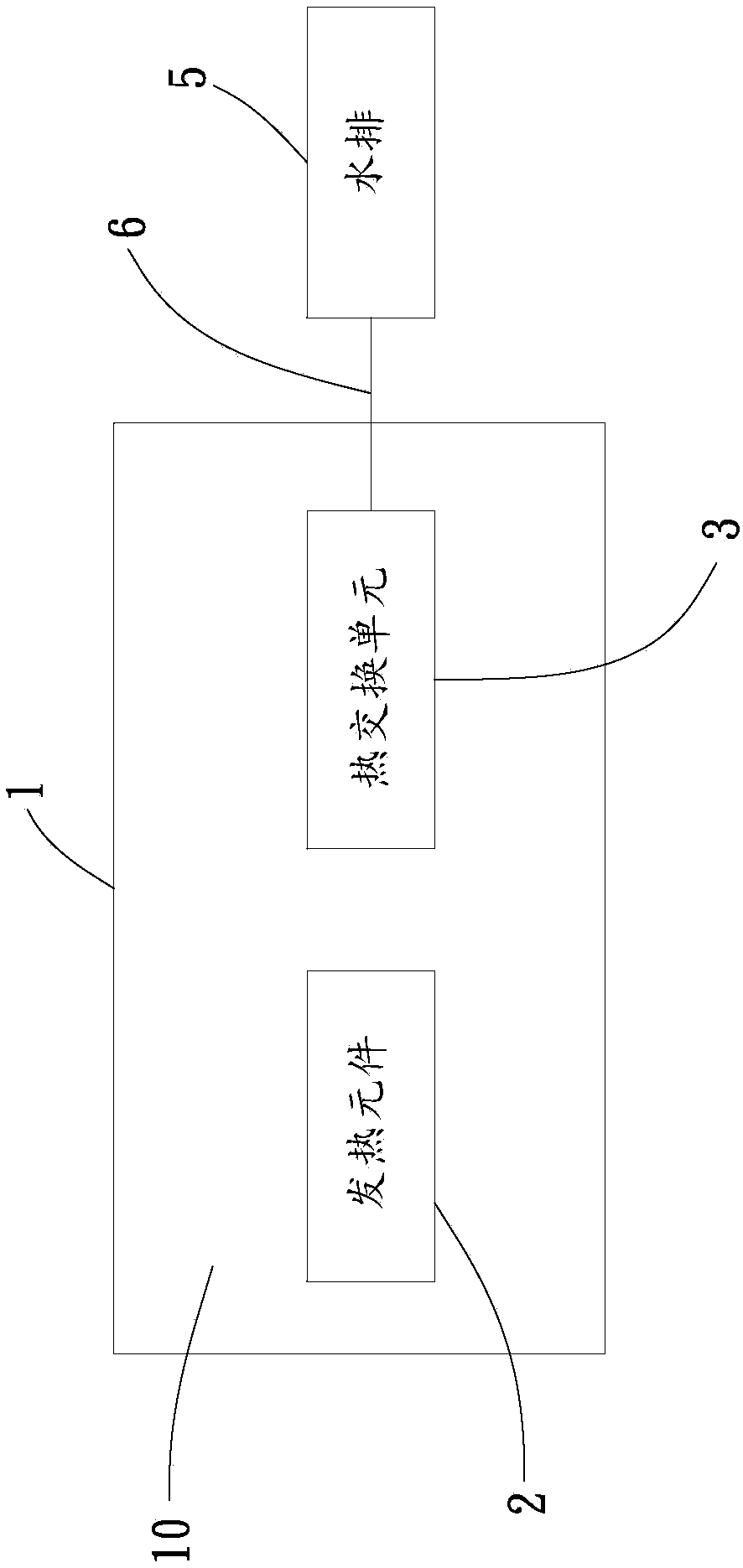
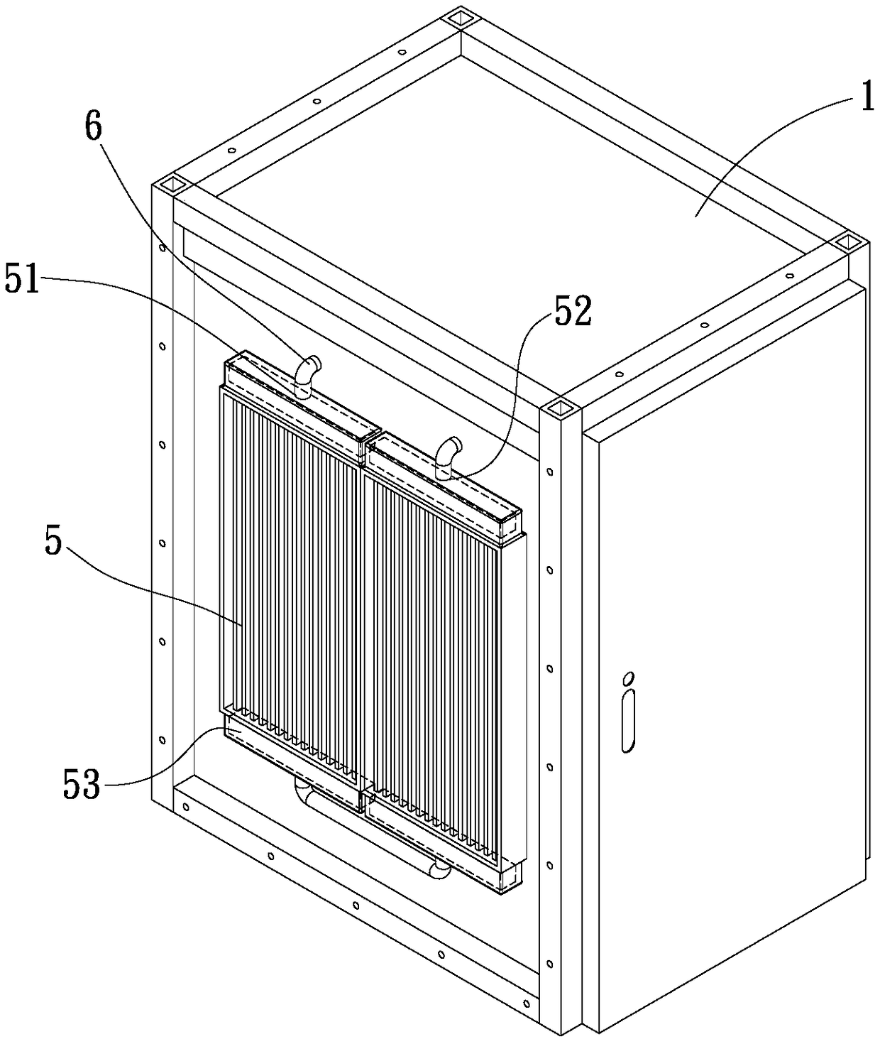
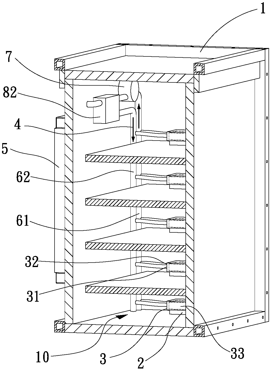
[0033] see figure 1 , figure 2 , image 3 , is a schematic block diagram, a three-dimensional combination view and a three-dimensional sectional view of the first embodiment of the heat dissipation cycle structure of the present invention. As shown in the figure, a heat dissipation cycle structure includes a body 1, at least one heat exchange unit 3, at least one water row 5 and at least one pump 7, the main body 1 has a closed accommodation space 10 to accommodate at least one heating element 2, in this embodiment, the main body 1 is a Chassis or cabinet (such as server cabinet, computer case (such as Figure 4 shown), etc.) for illustration, but not limited thereto, that is, any body 1 with a closed accommodation space 10 is provided with a heat generating element 2 (such as ...


PUM


Abstract

The invention provides a heat dissipation cycle structure. The heat dissipation cycle structure comprises a body, at least one heat exchange unit, at least one water blower and at least one pump; thebody is provided with a containing space for containing at least one heating element; the heat exchange unit is arranged in the containing space and is in contact with the heating element correspondingly; the water blower is arranged outside the body and connected with the heat exchange unit through at least one pipe body group; and the pump can be arranged either inside or outside the body and connected with the heat exchange unit and the water blower. Through the structural design of the heat dissipation cycle structure provided by the invention, the heat exchange efficiency and the heat dissipation efficiency can be greatly improved, and the modular effect is achieved.

Description

technical field [0001] The invention relates to a heat dissipation cycle structure, in particular to a heat dissipation cycle structure which can greatly improve heat dissipation efficiency. Background technique [0002] The advancement of science and technology can improve the convenience of human life, especially at present, all kinds of data processing and the use of the Internet rely on the operation of electronic equipment. Therefore, electronic equipment with high-speed processing performance and large storage energy is being used Widely used in various enterprises. [0003] Let’s take the traditional existing chassis (cabinet) structure that can accommodate various heating elements for IT, communication, industry, transportation, transportation, etc. as an illustration. The inside of the chassis (cabinet) is a closed accommodation space. The space can accommodate a plurality of heating elements (which can be a central processing unit (CPU), a microprocessor or a chip...

Claims


Application Information

Patent Timeline
IPC IPC(8): H05K7/20
CPCH05K7/20136H05K7/20272
Inventor 邱荣毅
Owner ASIA VITAL COMPONENTS SHENZHEN CO LTD
Learn More