
Slurry stirring device for coated fabric production

A stirring device and coating cloth technology, which is applied to mixers with rotating stirring devices, mixer accessories, transportation and packaging, etc., can solve the problem of time-consuming, agglomerated slurry pulverization and refinement, which affects the production of coated cloth Quality and other issues, to achieve the effect of improving quality, ensuring stable placement, and convenient and quick cleaning

Pending Publication Date: 2018-10-02
浙江唐艺织物整理有限公司
View PDF0 Cites 16 Cited by
  • Summary
  • Abstract
  • Description
  • Claims
  • Application Information

AI Technical Summary

Benefits of technology

This patented technology simplifies construction while providing ease of usage compared to previous methods. By creating an apparatus that mixes or grinds materials together without requiring manual labor, there's no longer any issues associated with traditional ways like adding water beforehand. Additionally, filters used inside the machine have improved filtering capabilities which help purify the resulting mixture better. These technical benefits contribute to improving productivity efficiency and reducing costs related to manufacturing processes such as coatings.

Problems solved by technology

This patented technical problem addressed by this patents relates to improving the efficiency at producing coatings on fabric during manufacturing processes while reducing defects such as streaks or unevenness that can occur when adding too much liquid (water) into thick layers containing aggregations).

Method used


Image

  • Slurry stirring device for coated fabric production
  • Slurry stirring device for coated fabric production
  • Slurry stirring device for coated fabric production

Examples


Embodiment Construction

[0018] The following will clearly and completely describe the technical solutions in the embodiments of the present invention with reference to the accompanying drawings in the embodiments of the present invention. Obviously, the described embodiments are only some, not all, embodiments of the present invention. Based on the embodiments of the present invention, all other embodiments obtained by persons of ordinary skill in the art without making creative efforts belong to the protection scope of the present invention.

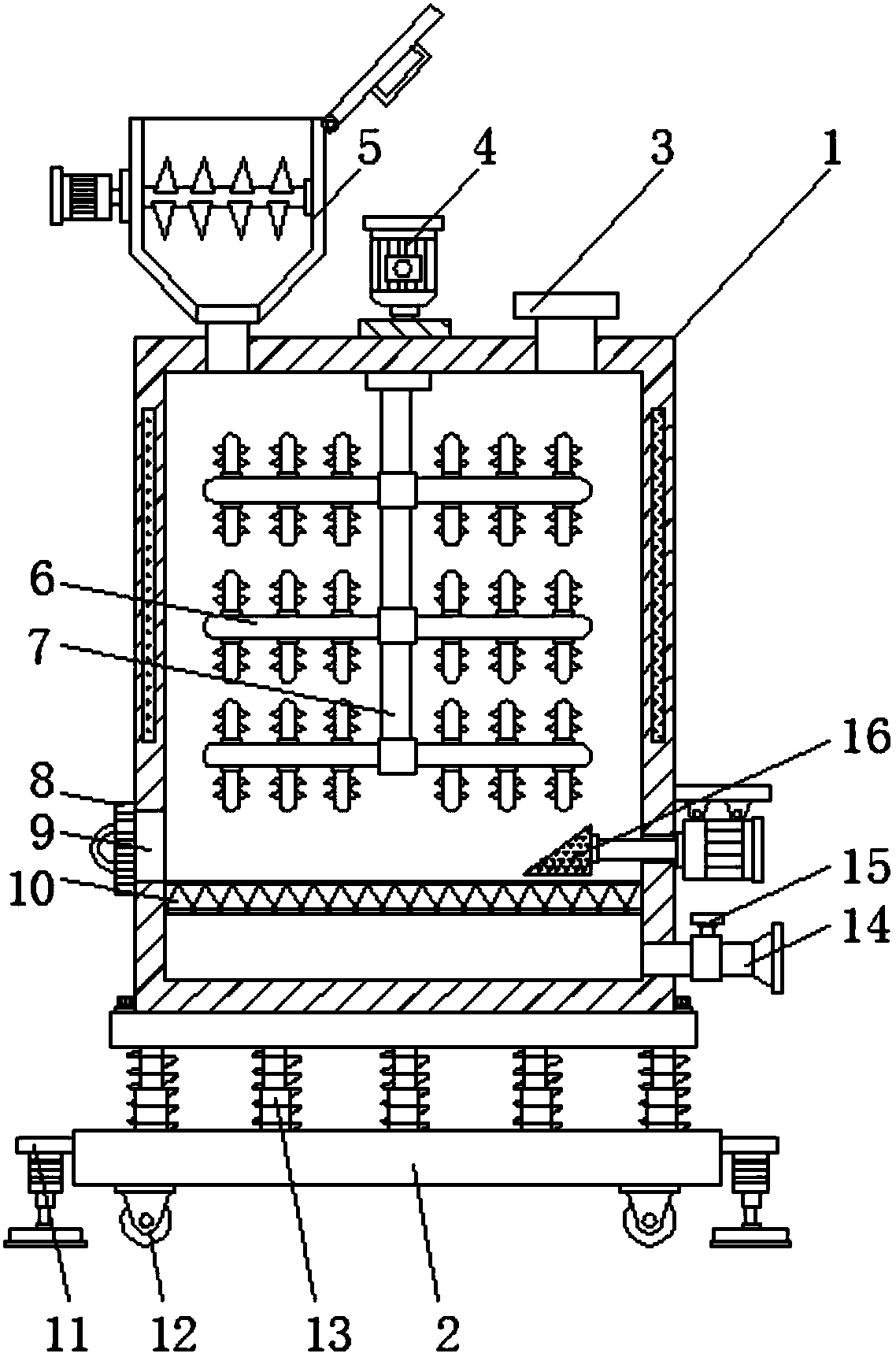
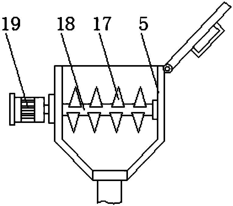
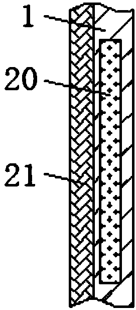
[0019] see Figure 1-6 , in an embodiment of the present invention, a slurry stirring device for coating cloth production includes a stirring box 1 and a base 2, the top sides of the stirring box 1 are respectively provided with a feeding hopper 5 and a water inlet 3, and the sides of the feeding hopper 5 A pulverizing motor 19 is installed on the wall, and the output shaft of the pulverizing motor 19 is connected with a pulverizing roller 18 through a speed r...


PUM


Abstract

The invention discloses a slurry stirring device for coated fabric production. The slurry stirring device comprises a stirring tank and a base and is characterized in that a feeding hopper and a wateradding port are respectively arranged on two sides of the top of the stirring tank, a crushing motor is mounted on the lateral wall of the feeding hopper, a crushing roller is connected to the outputshaft of the crushing motor through a reducer, crushing teeth are evenly distributed on the outer wall of the crushing roller, a filter screen is arranged at the bottom of the inner cavity of the stirring tank, an impurity cleaning push plate is arranged on the upper side of the filter screen, and the bottom of the stirring tank is fixedly connected with the base through damping spring columns. The slurry stirring device has the advantages that caked slurry can be crushed and refined before slurry stirring, slurry stirring time is reduced, impurities in the slurry can be removed through filtering by the aid of the filter screen arranged in the stirring tank, the quality of mixed slurry is increased, the impurity cleaning push plate arranged on the upper side of the filter screen can fastpush the impurities accumulated on the filter screen out of the stirring tank, and manual cleaning is not needed.

Description


Claims


Application Information

Patent Timeline
Owner 浙江唐艺织物整理有限公司
Learn More