Al technical title is built by PatSnap Al team. It summarizes the technical point description of the patent document.
A technology for cleaning device and section steel, which is applied in the direction of using liquid cleaning methods, cleaning methods and utensils, chemical instruments and methods, etc., which can solve the problems such as poor effect of steel ball turning, affecting the cleaning effect of steel balls, and poor turning effect. Achieve better cleaning effect, increase cleaning effect and increase contact area
Inactive Publication Date: 2018-10-02
当涂县金龙凤科技股份有限公司
View PDF0 Cites 1 Cited by
Summary
Abstract
Description
Claims
Application Information
AI Technical Summary
This helps you quickly interpret patents by identifying the three key elements:
Problems solved by technology
Method used
Benefits of technology
Problems solved by technology
[0005] Aiming at the deficiencies of the prior art, the present invention provides an improved cleaning device for steel balls, which solves the problem of the traditional steel ball cleaning device, the direction of rotation of the cleaning cylinder can only rotate in one direction, and the effect of turning over the steel balls inside the cleaning cylinder Not good, the turning effect is not good, so that the outer surface of the steel ball cannot fully contact with the water and the cleaning bump, which affects the cleaning effect of the steel ball, and the cleaning effect is not good.
Method used
Image
Click on the blue label to locate the original text in one second.
Reading with bidirectional positioning of images and text.
Examples
Embodiment Construction
[0026] The following will clearly and completely describe the technical solutions in the embodiments of the present invention with reference to the accompanying drawings in the embodiments of the present invention. Obviously, the described embodiments are only some, not all, embodiments of the present invention. Based on the embodiments of the present invention, all other embodiments obtained by persons of ordinary skill in the art without making creative efforts belong to the protection scope of the present invention.
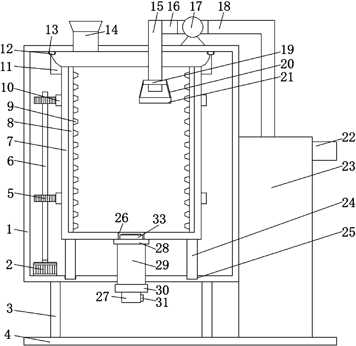
[0027] The embodiment of the present invention provides an improved steel ball cleaning device, such as Figure 1-3 As shown, the cleaning device body 1 is included, the bottom of the cleaning device body 1 is fixedly connected with a leg 3, the bottom of the leg 3 is fixedly connected with a substrate 4, and the top of the cleaning device body 1 is fixedly connected with a feed pipe 14, and the cleaning device body 1 The top of the inner wall is provided with...
PUM
Abstract
The invention provides an improved cleaning device for steel balls, and relates to the field of mechanical equipment. The improved cleaning device for the steel balls comprises a cleaning device body,supporting legs are fixedly connected to the bottom of the cleaning device body, the bottoms of the supporting legs are fixedly connected with a base plate, the top of the cleaning device body is fixedly connected with a feeding pipe, a sliding groove is formed in the top of the inner wall of the cleaning device body, and rotating columns are connected to the sliding groove in a sliding mode, thetops of the rotating columns are fixedly connected with a cleaning inner cylinder, and the outer surface of the cleaning inner cylinder is fixedly connected with limiting blocks and two racks correspondingly. According to the improved cleaning device for the steel balls, a rotating shaft is driven to rotate through starting of a forward and reverse rotation motor, and drives gears to rotate; andthe gears, the racks, the rotating columns and the sliding groove cooperate with one another for use so that the cleaning inner cylinder can rotate, the rotation of the cleaning inner cylinder drivesthe steel balls which are placed into the cleaning inner cylinder to roll, friction is generated between the steel balls and convex blocks, and then the surfaces of the steel balls are cleaned.
Description
technical field [0001] The invention relates to the technical field of mechanical equipment, in particular to an improved cleaning device for steel balls. Background technique [0002] Steel ball is a kind of metal abrasive, the main varieties are stainless steel shot, cast steel shot, aluminum shot, steel wire cut shot, grinding shot, copper shot, steel ball is widely used in non-ferrous metal die castings, castings, aluminum profiles, auto parts, machinery Surface treatment in manufacturing, hardware, pump and valve industries. It mainly focuses on removing scale on the surface of the product, burrs on the edge surface, surface roughening, matt suburban fruit, leveling and strengthening, and rust removal treatment. The most widely used product in steel balls is stainless steel shot, which is commonly known as stainless steel wire cut shot. Refined by cutting, rounding and other processes, the appearance is bright and rust-free, bead-shaped (cut pills, cylindrical). Stain...
Claims
Application Information
Patent Timeline
Application Date:The date an application was filed.
Publication Date:The date a patent or application was officially published.
First Publication Date:The earliest publication date of a patent with the same application number.
Issue Date:Publication date of the patent grant document.
PCT Entry Date:The Entry date of PCT National Phase.
Estimated Expiry Date:The statutory expiry date of a patent right according to the Patent Law, and it is the longest term of protection that the patent right can achieve without the termination of the patent right due to other reasons(Term extension factor has been taken into account ).
Invalid Date:Actual expiry date is based on effective date or publication date of legal transaction data of invalid patent.