Sprue-riser removal machine

A technology of pouring risers and ports, applied in the field of pouring and riser removal machines, can solve the problems of limited operation range and equipment loss, and achieve the effect of convenient use

Inactive Publication Date: 2018-10-02
李志护
View PDF0 Cites 0 Cited by
  • Summary
  • Abstract
  • Description
  • Claims
  • Application Information

AI Technical Summary

Problems solved by technology

[0004] Aiming at the deficiencies existing in the prior art, the object of the present invention is to provide a pouring riser removal machine to solve the existing problem of using the pouring riser removal machine because it needs to be connected to an external inflatable device to separate it. This limits the scope of operation. If the machine is still running when it is not in use, and you forget to turn it off, it is easy to cause unnecessary wear and tear on the equipment.

Method used


Image

  • Sprue-riser removal machine
  • Sprue-riser removal machine
  • Sprue-riser removal machine

Examples


Embodiment Construction

[0024] In order to make the technical means, creative features, goals and effects achieved by the present invention easy to understand, the present invention will be further described below in conjunction with specific embodiments.

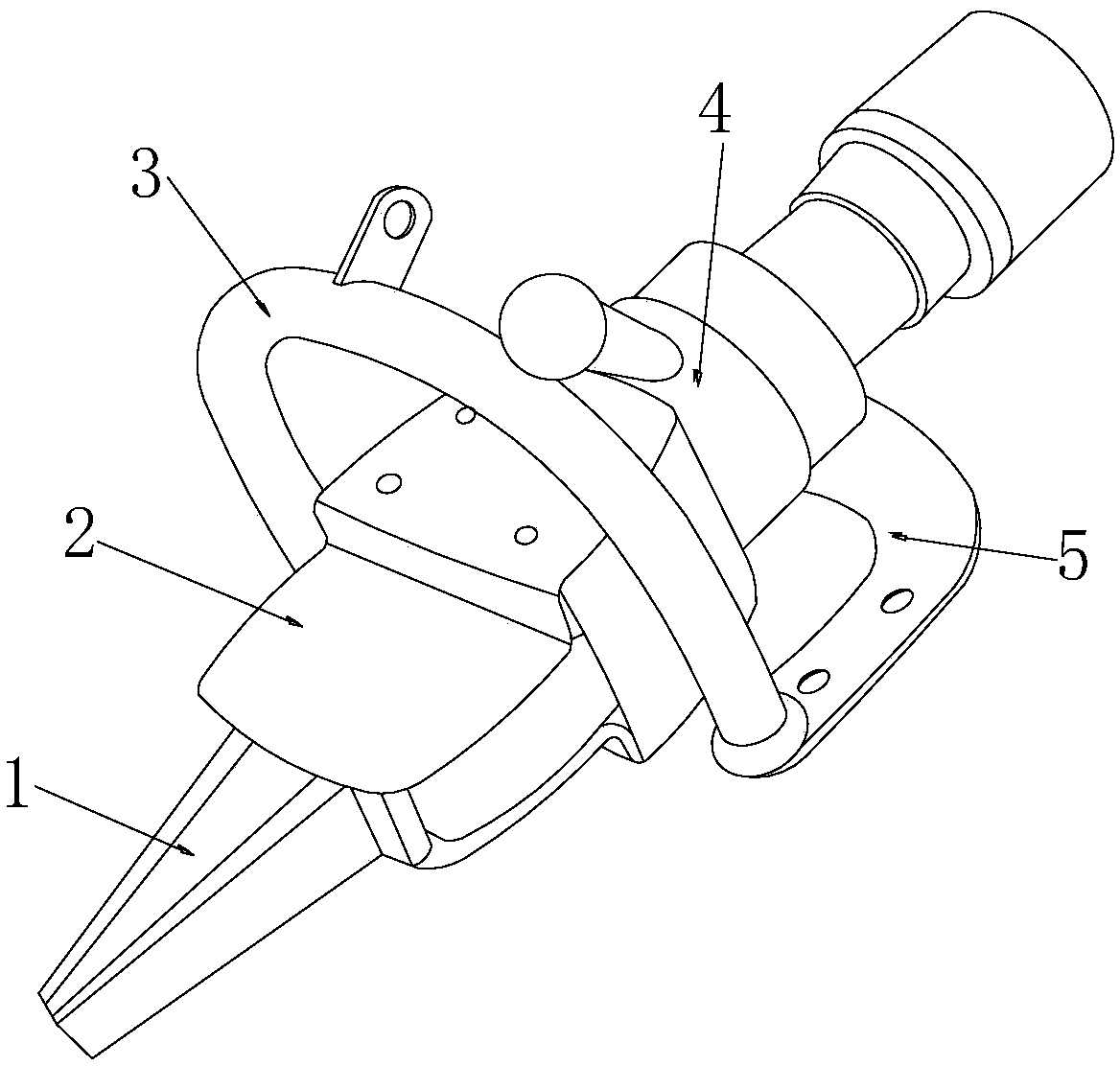
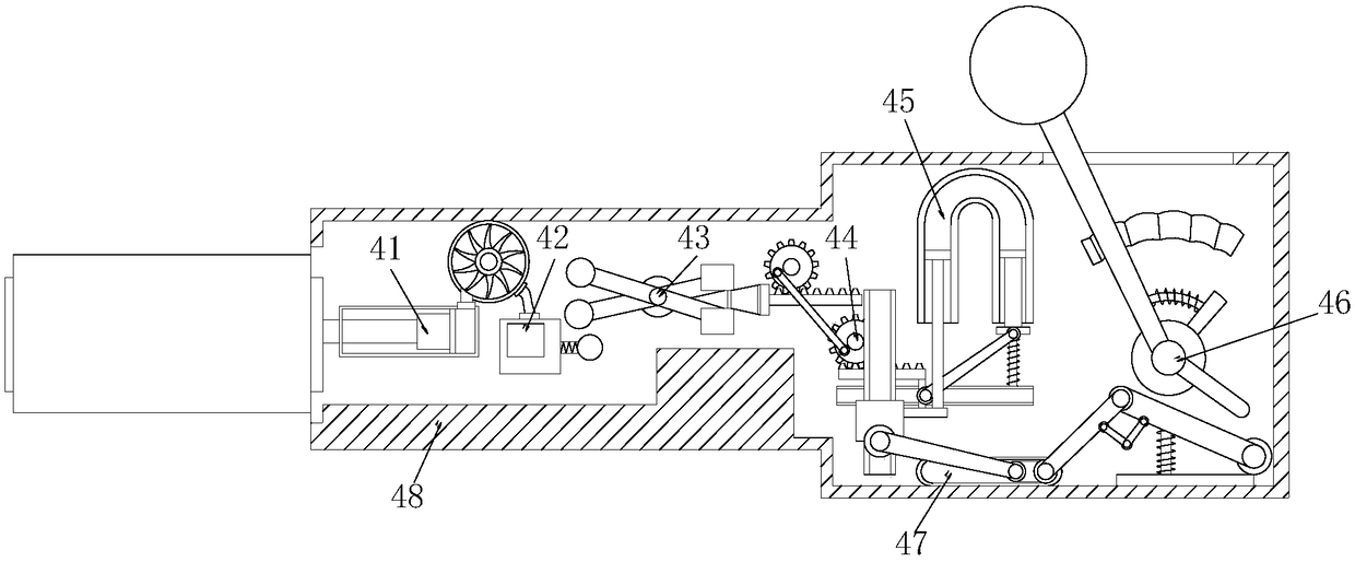
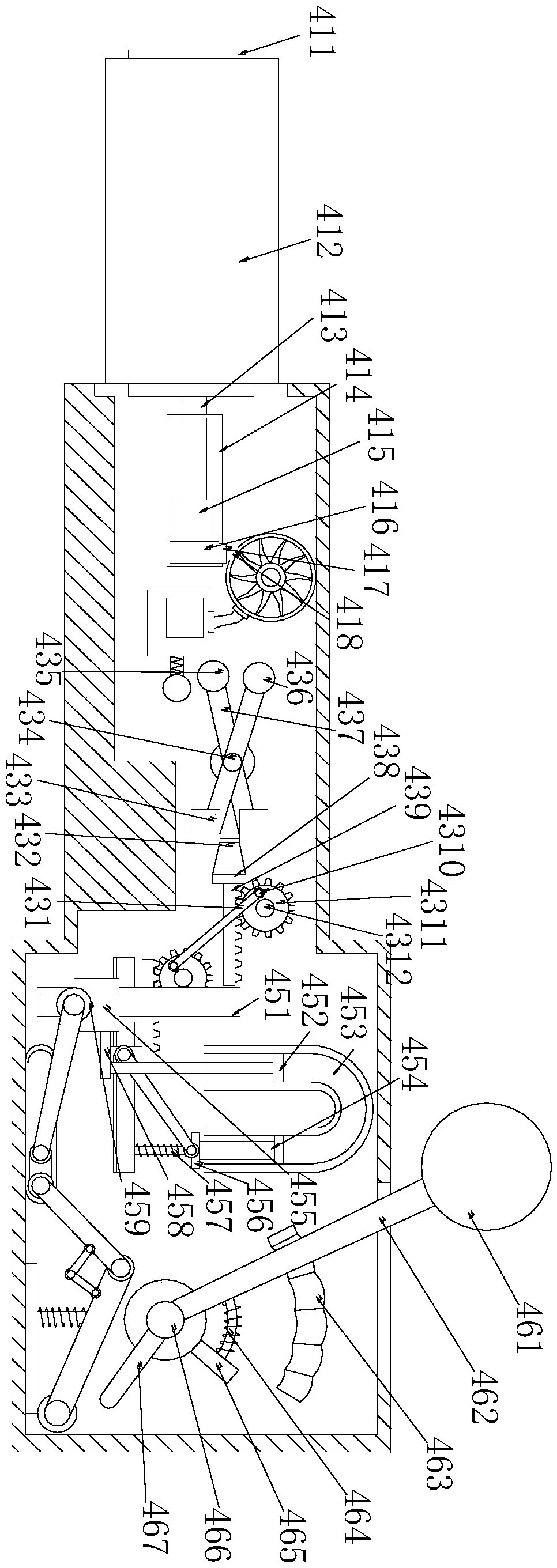
[0025] see figure 1 , figure 2 , image 3 , Figure 4 , the present invention provides a technical solution for a pouring riser removal machine: its structure includes a separation head 1, a positioning port 2, a handle 3, an inflation separation control device 4, a support block 5,

[0026] The separation head 1 is embedded and installed inside the positioning port 2, the handle 3 is welded to the outer surface of the support block 5, the positioning port 2 is connected to the inflation separation control device 4, and the support block 5 is installed on the inflation separation control device 4 the outer surface, the separation head 1 is connected to the pneumatic separation control device 4 through the positioning port 2;

[0027] The infla...


PUM


Abstract

The invention discloses a sprue-riser removal machine. The sprue-riser removal machine structurally comprises a separating head, a positioning port, a handle, an inflatable separation control device and a supporting block. The sprue-riser removal machine is characterized in that the separating head is installed in the positioning port in an embedded mode and connected with the inflatable separation control device through the positioning port; the inflatable separation control device comprises a pneumatic pushing device, a to-be-triggered inflator pump, a pushing trigger assembly, a gear pushing assembly, a U-shaped extrusion channel, a manual control rocker, an extrusion sliding assembly and a protection shell; the pneumatic pushing device is connected with the to-be-triggered inflator pump; the pushing trigger assembly is installed inside the protection shell; the gear pushing assembly is connected with the U-shaped extrusion channel; the manual control rocker is arranged above the extrusion sliding assembly; and the gear pushing assembly is connected with the pushing trigger assembly. The sprue-riser removal machine can be simply started through external force as needed, and canrun without being connected with external equipment, the operation range is not limited, and the sprue-riser removal machine can be used more conveniently.

Description

technical field [0001] The invention relates to a pouring riser removing machine, which belongs to the field of pouring riser removing machines. Background technique [0002] The riser refers to the supplementary part added to the top or side of the casting to avoid defects in the casting. In the mold, the cavity of the riser is a container for storing liquid metal. Its functions are various and different. The riser has different forms, sizes and opening positions. Therefore, the design of the riser should consider the properties of the casting alloy and the characteristics of the casting. [0003] But this prior art is when using pouring riser removal machine, because it needs to be connected with the external inflatable equipment to carry out its separation work, like this comparatively limits the scope of operation, if need not use, machine is still running, and forgets to put When it is turned off, it is easier to cause unnecessary wear and tear to its equipment. Cont...

Claims


Application Information

Patent Timeline
Patent Type & Authority Applications(China)
IPC IPC(8): B22D31/00
CPCB22D31/00
Inventor 李志护
Owner 李志护
Why Eureka
Try Eureka