
Tool for disassembling and assembling nut of metallurgy mechanical device

A technology for mechanical equipment and nuts, which is applied in the field of metallurgical machinery and equipment nut removal tools, can solve the problems of switching back and forth, trouble, damage, and large operating space, etc., to achieve the effect of easy disassembly and assembly of nuts, ensuring a safe distance, and avoiding damage

Inactive Publication Date: 2018-10-02
繁昌县亘通智能装备有限公司
View PDF5 Cites 3 Cited by
  • Summary
  • Abstract
  • Description
  • Claims
  • Application Information

AI Technical Summary

Problems solved by technology

[0003] The traditional nut removal tool has a simple structure and can only complete the quick installation and disassembly of a single-size nut. However, due to structural defects, the ordinary wrench is very troublesome and laborious to install and disassemble, and it is easy to cause the nut to slip and be damaged. Larger operating space, and the size of the nuts of many existing connecting bolts is different, and the number is large, it is troublesome to switch back and forth, and it is very troublesome to install the nuts in some narrow corners. Therefore, for the above The problem proposes a metallurgical machinery and equipment nut removal tool

Method used


Image

  • Tool for disassembling and assembling nut of metallurgy mechanical device
  • Tool for disassembling and assembling nut of metallurgy mechanical device
  • Tool for disassembling and assembling nut of metallurgy mechanical device

Examples


Embodiment Construction

[0019] The following will clearly and completely describe the technical solutions in the embodiments of the present invention with reference to the accompanying drawings in the embodiments of the present invention. Obviously, the described embodiments are only some, not all, embodiments of the present invention. Based on the embodiments of the present invention, all other embodiments obtained by persons of ordinary skill in the art without making creative efforts belong to the protection scope of the present invention.

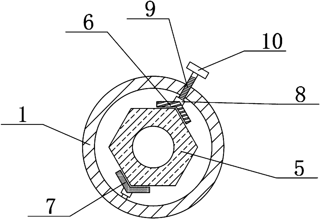
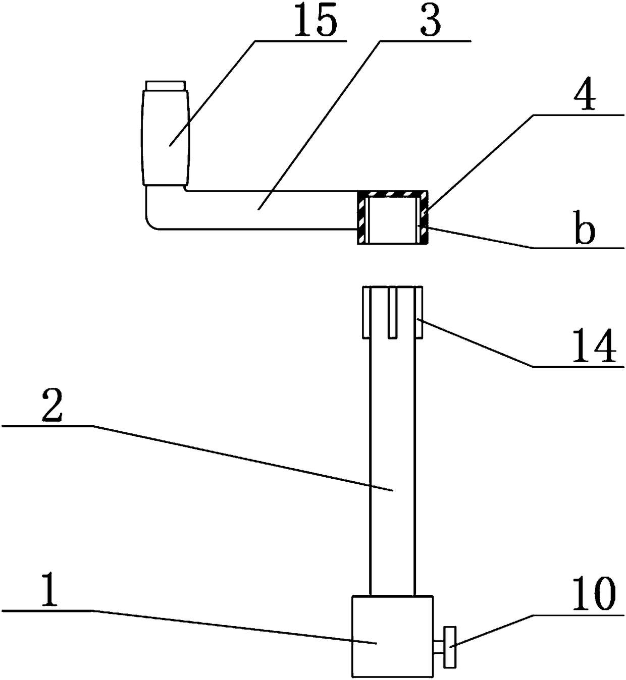
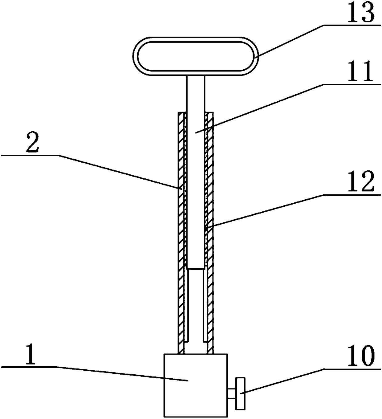
[0020] see Figure 1-4 , the present invention provides a technical solution:

[0021] A nut removal tool for metallurgical mechanical equipment, comprising a casing 1, a main shaft 11, a handle 3 and a nut 5, the top of the casing 1 is fixedly connected with a main body 2, and the outer wall of the top end of the main body 2 is fixedly connected with a Blocks 14 evenly distributed in the axial direction, the blocks 14 are elongated, the inner wall of the mai...


PUM


Abstract

The invention relates to the technical field of disassembling and assembling tools, in particular to a tool for disassembling and assembling a nut of a metallurgy mechanical device. The tool comprisesa sleeve pipe, a main shaft, a crank and the nut; a main pipe body is fixedly connected to the top end of the sleeve pipe, clamping blocks which are uniformly distributed in the axial direction are fixedly connected to the outer side wall of the top end of the main pipe body, and sliding grooves are formed in the inner wall of the main pipe body; the main shaft is slidably connected to the innerside of the main pipe body, a rotating rod is fixedly connected to the top end of the main shaft, and a clamping pipe is fixedly connected to the top end of the crank; a fixed clamping plate is fixedly connected to the inner side wall of the sleeve pipe, and a movable clamping plate is arranged at the position, symmetric with the fixing clamping plate, of the inner side wall of the sleeve pipe; and one end, close to the inner wall of the sleeve pipe, of the movable clamping plate is rotationally connected to a rotating ring, the other end of the rotating ring is fixedly connected to a screw rod, and the tail end of the screw rod penetrates out of the sleeve pipe and is fixedly connected to an adjusting knob. According to the tool for disassembling and assembling the nut of the metallurgy mechanical device, the structure is scientific, operation is labor-saving, the working efficiency can be effectively improved, and the tool has the huge economic benefits and the wide market requirements and is worthy of popularization.

Description

technical field [0001] The invention relates to the technical field of dismounting tools, in particular to a nut dismounting tool for metallurgical machinery and equipment. Background technique [0002] Heavy machinery manufacturing is an important industry related to the lifeline of the national economy and national security. With the development of society, heavy machinery manufacturing has been paid more and more attention by people, and metallurgical machinery and equipment are part of the heavy machinery manufacturing industry. Metallurgical machinery There are a large number of nuts in the equipment, so when disassembling and installing the nuts, it is necessary to use round nut removal tools. With the development of science and technology, different types of round nut removal tools for metallurgical machinery and equipment have appeared on the market. Therefore, There is an increasing demand for nut removal tools for metallurgical machinery and equipment. [0003] Th...

Claims


Application Information

Patent Timeline
IPC IPC(8): B25B27/14
CPCB25B27/14
Inventor 不公告发明人
Owner 繁昌县亘通智能装备有限公司
Features
  • Generate Ideas
  • Intellectual Property
  • Life Sciences
  • Materials
  • Tech Scout
  • Unparalleled Data Quality
  • Higher Quality Content
  • 60% Fewer Hallucinations
Learn More