Simple and convenient disassembling and assembling device of horizontal flange connecting device

A connecting device, horizontal technology, applied in the field of disassembly and assembly devices, can solve the problems of high cost, time-consuming and laborious disassembly and assembly, and inconvenience, and achieve the effects of low cost, high efficiency, and convenient disassembly and assembly.

Inactive Publication Date: 2018-10-02
徐桂根
View PDF0 Cites 2 Cited by
  • Summary
  • Abstract
  • Description
  • Claims
  • Application Information

AI Technical Summary

Problems solved by technology

[0003] The purpose of the present invention is to solve the defects of high cost, time-consuming, laborious and inconvenient disassembly and assembly that need to use lifting equipment when disassembling and assembling flange connection equipment, and provide a simple and convenient disassembly and assembly device for horizontal flange connection equipment , its disassembly and assembly no longer need lifting equipment and save time, effort and money

Method used


Image

  • Simple and convenient disassembling and assembling device of horizontal flange connecting device
  • Simple and convenient disassembling and assembling device of horizontal flange connecting device
  • Simple and convenient disassembling and assembling device of horizontal flange connecting device

Examples


Embodiment 1

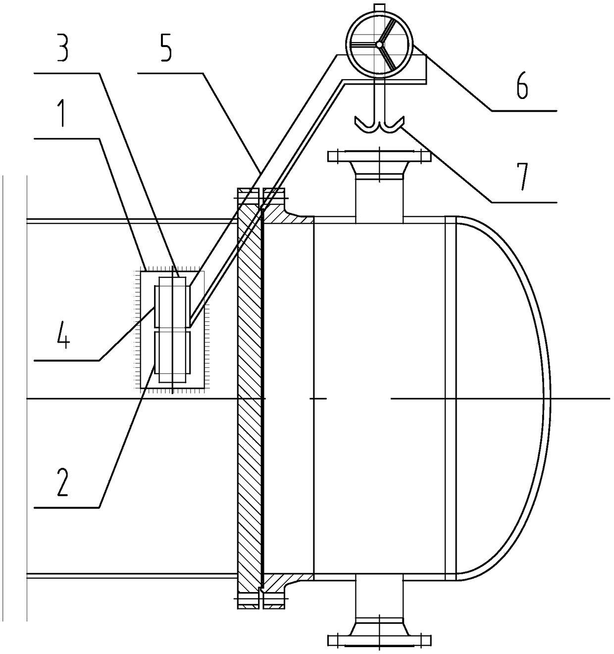
[0019] like figure 1 Shown: The flange connection equipment is a new horizontal heat exchanger, which includes two parts, the shell side and the tube box. One side of the shell side is provided with a connecting plate 1, the bearing seat 2 is directly welded on the connecting plate 1, and the shaft 3 is installed On the bearing seat 2, the shaft sleeve 4 is set on the shaft 3, the boom 5 is set obliquely, the lower end is connected with the shaft sleeve 4, and the upper end is provided with a manual worm gear screw lifter 6 and a hook 7, and the hook 7 is connected to the worm gear wire The lifting screw mandrel of rod lifter 6 is connected.

[0020] The new horizontal heat exchanger of this embodiment is disassembled and then reassembled for on-site inspection and maintenance as follows:

[0021] ①Weld the bearing seat 2 directly to the connecting plate 1 on the side of the shell, connect the hook 7 and the pipe box on the right side of the flange with a wire rope, and turn ...

Embodiment 2

[0025] The flange connection equipment is an old horizontal heat exchanger, and its shell-side cylinder is allowed to be welded. Others are the same as in Embodiment 1.

[0026] The on-site maintenance of this embodiment is completely the same as that of Embodiment 1 when it is first dismantled and then reassembled.

Embodiment 3

[0028] The flange connection equipment is an old horizontal heat exchanger, and its shell-side cylinder is not allowed to be welded. Others are the same as in Embodiment 1.

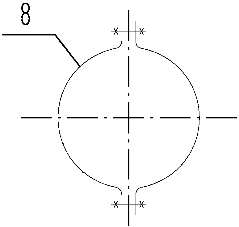
[0029] In this embodiment, when on-site maintenance is first dismantled and then reassembled, if figure 2 As shown, a clamp 8 is prefabricated first and the clamp 8 is fastened on the shell side cylinder, and then the connecting plate 1 is welded to the clamp, and the rest is completely the same as that of embodiment 1.


PUM


Abstract

The invention particularly relates to a simple and convenient disassembling and assembling device of a horizontal flange connecting device. The disassembling and assembling device is characterized bycomprising a suspension arm, a shaft, a bearing seat, a shaft sleeve, a lifting hook and a lifting hook lifting device; and the shaft is installed on the bearing seat; the shaft sleeve sleeves the shaft, the lower end of the suspension arm is connected with the shaft sleeve, and the lifting hook and the lifting hook lifting device are arranged at the upper end of the suspension arm. The device hasthe advantages of being simple in structure, low in cost, flexible and convenient to use and high in efficiency; by the adoption of the device, a lifting device does not need to be used, so that thedisassembling and assembling cost is greatly reduced; and according to the device, the size is small, the limit of height of a road and a device and the limit of the space to the device are small, disassembling and assembling of the device on site are very convenient, and the disassembling and assembling efficiency can be greatly improved.

Description

technical field [0001] The invention specifically relates to a simple disassembly device for horizontal flange connection equipment. Background technique [0002] In industrial production, there are many devices that can be disassembled through flange connections. During the assembly or disassembly of the two parts to be connected, lifting equipment (driving, truck crane, back chain, etc.) is required. Especially during the maintenance of the device, due to the limitation of the road, the height of the device, the space, etc., it is extremely troublesome to disassemble and assemble at the device site. Contents of the invention [0003] The purpose of the present invention is to solve the defects of high cost, time-consuming, laborious and inconvenient disassembly and assembly that need to use lifting equipment when disassembling and assembling flange connection equipment, and provide a simple and convenient disassembly and assembly device for horizontal flange connection ...

Claims


Application Information

Patent Timeline
Patent Type & Authority Applications(China)
IPC IPC(8): B66C1/14
CPCB66C1/14
Inventor 徐桂根
Owner 徐桂根
Why Eureka
Try Eureka