Deceleration belt capable of automatically judging vehicle speeds

A technology of automatic judgment and speed bumps, applied in the directions of roads, road signs, traffic signals, etc., can solve the problem that speed bumps cannot be automatically retracted, and achieve the effect of simple and ingenious structure and strong practicability.

Active Publication Date: 2018-10-02
丁柳朋
View PDF5 Cites 13 Cited by
  • Summary
  • Abstract
  • Description
  • Claims
  • Application Information

AI Technical Summary

Problems solved by technology

[0005] In view of the above situation, in order to overcome the defects of the prior art, the present invention provides a deceleration belt that can automatically judge the vehicle speed, which effectively solves the problem that the current deceleration belt cannot be automatically retracted according to the vehicle speed

Method used


Image

  • Deceleration belt capable of automatically judging vehicle speeds
  • Deceleration belt capable of automatically judging vehicle speeds
  • Deceleration belt capable of automatically judging vehicle speeds

Examples


Embodiment Construction

[0014] The specific implementation manners of the present invention will be described in further detail below in conjunction with the accompanying drawings.

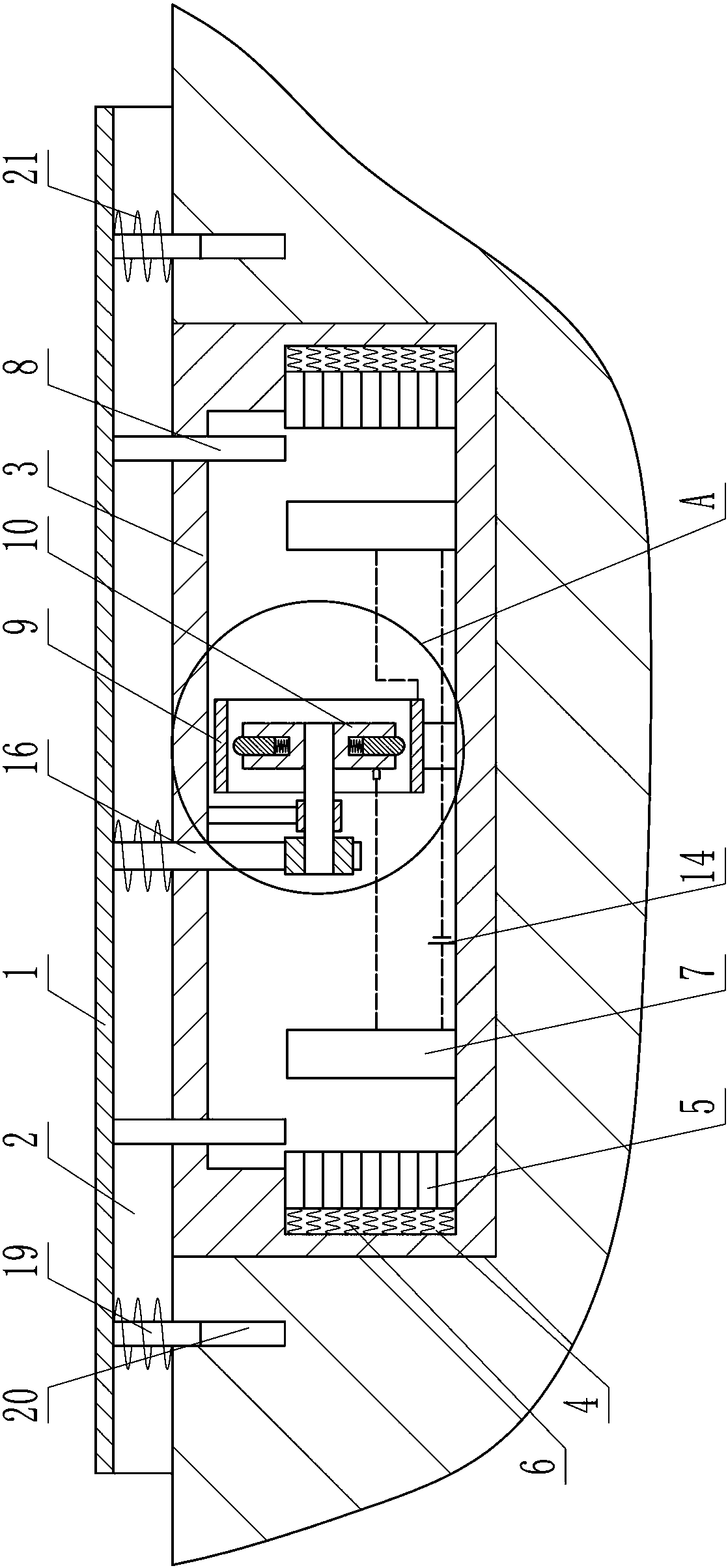
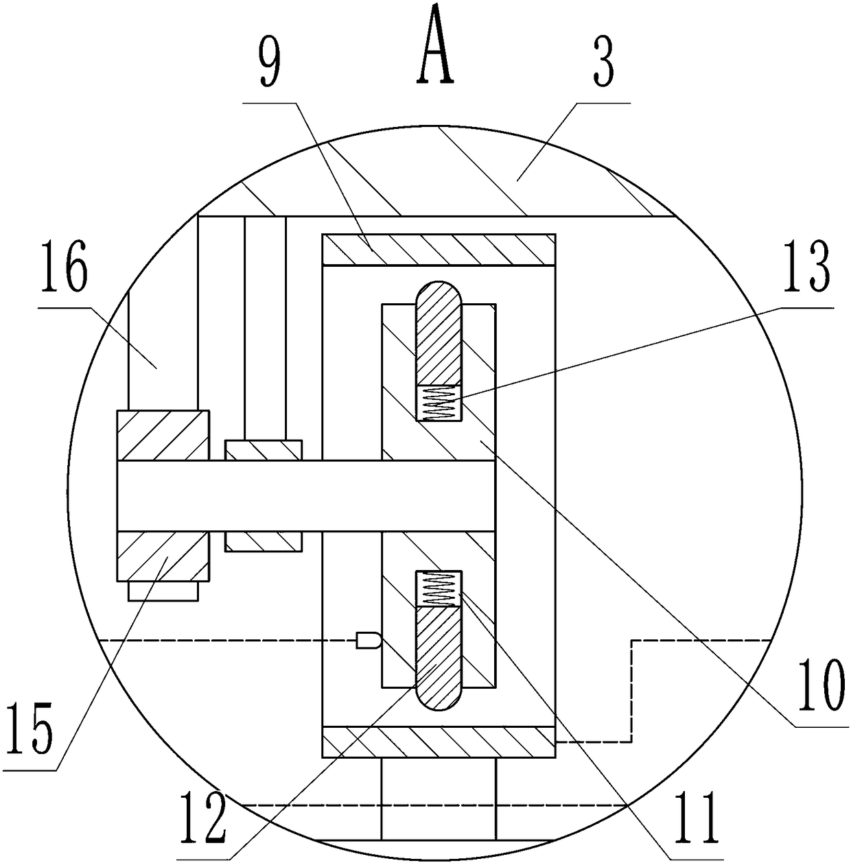
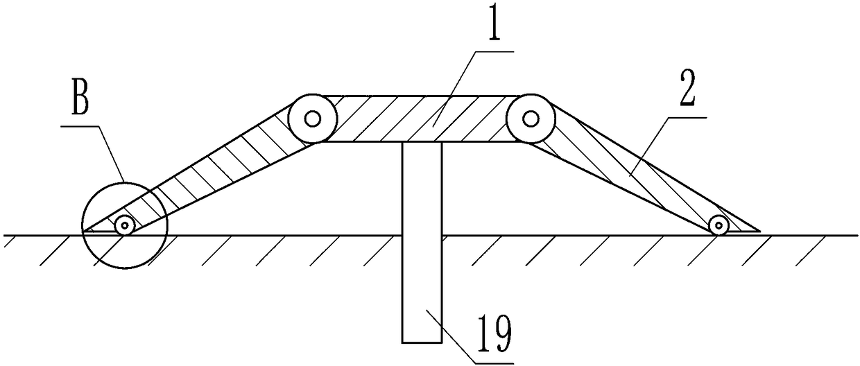
[0015] Depend on Figure 1 to Figure 4 Given, the present invention includes the speed bump body, the speed bump body includes a horizontal top plate 1, a side plate 2 of the same length is hinged on the front and rear edges of the top plate 1, and the opposite side of the hinged side of the side plate 2 hangs freely. On the road surface, two side plates 2 and a top plate 1 form a trapezoidal structure in section; a plurality of compression springs 21 are installed under the top plate 1;

[0016] There is a box body 3 under the speed bump body, and a vertical rectangular slot 4 is opened on the left and right side walls of the box body 3, and a plurality of stoppers made of magnetic materials are stacked up and down in each rectangular slot 4. plate 5, a first extension spring 6 is connected between each baffle plate 5 ...


PUM


Abstract

The invention relates to a deceleration belt capable of automatically judging vehicle speeds and the problem that the existing vehicle speed can not retract automatically is effectively solved. According to the technical scheme, the deceleration belt includes a deceleration belt body capable of being pressed downwards; a box body is arranged below the deceleration belt body and rectangular groovesare formed in the left lateral wall and the right lateral wall of the box body; a plurality of baffles arranged in each rectangular groove in a stacking up-and-down mode and fist tension springs areconnected the baffles and the rectangular grooves; an electromagnet is arranged on the outer of each rectangular groove and a horizontal and conductive ring sleeve is arranged in the box body; a rotating disc is arranged in the ring disc and a sliding block is arranged on the rotating disc; and the rotating disc and the sliding block are conductive; the deceleration belt is pressed downwards to drive the rotating disc to rotate, so that the sliding block moves outwards due to centrifugal force and is in contact with the inner wall, and therefore the electromagnets are electrified and the baffles are absorbed to drive the deceleration belt body. The deceleration belt can automatically adapt to the vehicle speeds, is intelligent and efficient and is simple and ingenious in structure and highin practicability.

Description

technical field [0001] The invention relates to the field of road facilities, in particular to a speed bump that can automatically determine vehicle speed. Background technique [0002] The speed bump is a traffic facility installed on the road to slow down passing vehicles. It is generally strip-shaped, and the material is mainly rubber or metal. It is generally yellow and black to attract visual attention. It is suitable for school intersections, community intersections and traffic crossroads. It is usually necessary to set speed bumps in places such as entrances. Speed ​​bumps decelerate by affecting the driver's psychology. When the vehicle passes through the speed bump at a higher speed, severe vibrations will be transmitted from the wheels to the driver through the body and seat. In order to reduce vehicle bumps, tires and suspension systems If there is any damage, the driver needs to brake to slow down and pass slowly, so as to play a role in deceleration. [0003] ...

Claims


Application Information

Patent Timeline
Patent Type & Authority Applications(China)
IPC IPC(8): E01F9/529
CPCE01F9/529
Inventor 田舒方刘以恒
Owner 丁柳朋
Why Eureka
Try Eureka