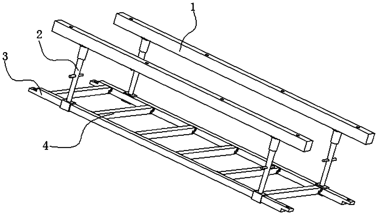
House ceiling mounting structure

A technology for installing structures and suspended ceilings, applied to ceilings, building components, building structures, etc., can solve problems such as unbalanced force exerted by workers at heights, falling, etc., achieve good positioning effects, prolong service life, and improve the effect of fixing force

Inactive Publication Date: 2018-10-02
WENZHOU POLYTECHNIC
View PDF6 Cites 0 Cited by
  • Summary
  • Abstract
  • Description
  • Claims
  • Application Information

AI Technical Summary

Problems solved by technology

[0005] The purpose of the present invention is to provide a ceiling installation structure of a house, which is positioned and lifted by the gap between the U-shaped clamping plate and the main keel, and the main keel is lifted, and the auxiliary keel is supported by the supporting block of the U-shaped structure on one side of the main keel. The arc surface structure on the block facilitates the adjustment of the angle of the auxiliary keel, reduces the force exerted by workers during installation, and has a good positioning effect, which solves the problem of falling due to excessive height and unbalanced force exerted by workers during installation

Method used


Image

  • House ceiling mounting structure
  • House ceiling mounting structure
  • House ceiling mounting structure

Examples


Embodiment Construction

[0035] The following will clearly and completely describe the technical solutions in the embodiments of the present invention with reference to the accompanying drawings in the embodiments of the present invention. Obviously, the described embodiments are only some, not all, embodiments of the present invention. Based on the embodiments of the present invention, all other embodiments obtained by persons of ordinary skill in the art without creative efforts fall within the protection scope of the present invention.

[0036] In describing the present invention, it is to be understood that the terms "opening", "upper", "lower", "thickness", "top", "middle", "length", "inner", "surrounding" etc. Indicating orientation or positional relationship is only for the convenience of describing the present invention and simplifying the description, and does not indicate or imply that the components or elements referred to must have a specific orientation, be constructed and operated in a sp...


PUM


Abstract

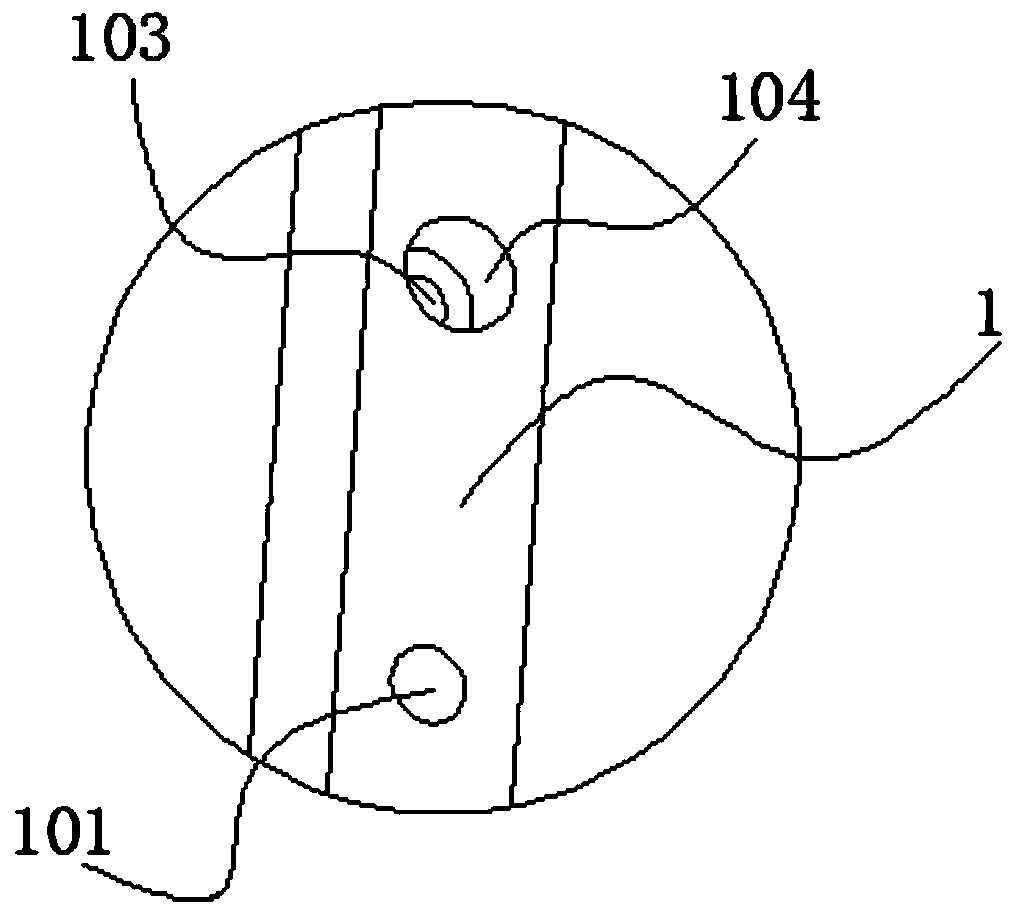
The invention discloses a house ceiling mounting structure and relates to the technical field of ceiling mounting. The house ceiling mounting structure comprises base columns, hanging parts, main keels and auxiliary keels. Two threaded holes are formed in one surface of each base column and are each of a blind opening structure; each hanging part comprises a hanging column and a reinforcing sleeve, the cross section of each hanging column is of an inverted trapezoidal structure, a threaded rod is fixed to one end of each hanging column, the threaded rods and the threaded holes are in threadedfit, and a U-shaped clamping plate is fixed to the other end of each hanging column; and each reinforcing sleeve is of a conical sleeve structure, the reinforcing sleeves are connected to the outer surfaces of the hanging columns in a sleeving mode, and a flange ring is fixed to one end of each reinforcing sleeve. According to the house ceiling structure, through clearance fit of the U-shaped clamping plates and the main keels, the main keels are positioned and lifted; the auxiliary keels are supported through supporting blocks of the U-shaped structures on one sides of the main keels, and theangles of the auxiliary keels are conveniently adjusted through arc surface structures on the supporting blocks, so that the forced applied by workers is reduced during mounting; and the positioningeffect is good, and the problem that during mounting, the height is excessively large, force applying of the workers is unbalanced, and consequently the workers fall is solved.

Description

technical field [0001] The invention belongs to the technical field of suspended ceiling installation, and in particular relates to a suspended ceiling installation structure of a house. Background technique [0002] Home decoration ceiling is a common link in home decoration. The classification of the ceiling is different according to the material of the decorative board. The ceiling decoration material is the main basis for distinguishing the name of the ceiling. There are mainly: light steel keel gypsum board ceiling, gypsum board ceiling, mineral wool board Suspended ceiling, splint suspended ceiling, special-shaped strip aluminum gusset ceiling, square painted aluminum gusset ceiling, painted glass ceiling, aluminum honeycomb perforated sound-absorbing panel ceiling, whole room duplex ceiling, etc. [0003] When installing the existing ceiling, the staff stand on the scaffolding for construction. However, during the construction and installation, the workers need to lif...

Claims


Application Information

Patent Timeline
Patent Type & Authority Applications(China)
IPC IPC(8): E04B9/00E04B9/06E04B9/12E04B9/18
CPCE04B9/00E04B9/06E04B9/12E04B9/18
Inventor 卓菁
Owner WENZHOU POLYTECHNIC
Why Eureka
Try Eureka