Lamp control circuit and lamp control method

A control method and circuit technology, applied in the field of lighting

Pending Publication Date: 2018-10-02
BEIJING XIAOMI MOBILE SOFTWARE CO LTD +1
View PDF13 Cites 1 Cited by
  • Summary
  • Abstract
  • Description
  • Claims
  • Application Information

AI Technical Summary

Problems solved by technology

[0004] The first purpose of the present invention is to provide a light control circuit to solve the problem that the same light cannot meet different needs of users in different application scenarios
[0005] The second purpose of the present invention is to provide a control method for lamps to solve the problem that the same lamp cannot meet different needs of users in different application scenarios

Method used


Image

  • Lamp control circuit and lamp control method
  • Lamp control circuit and lamp control method
  • Lamp control circuit and lamp control method

Examples


Embodiment 1

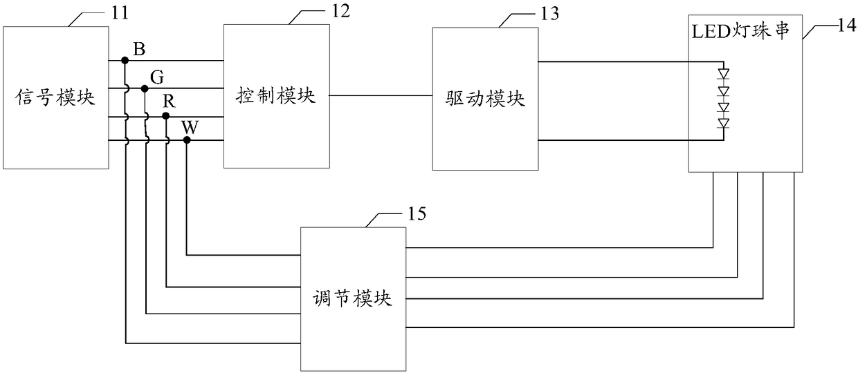
[0049] figure 1 It is a structural block diagram of a light control circuit shown according to an exemplary embodiment, and the light control circuit includes:

[0050] The signal module 11 is used to output the control signal, the control signal includes K channels of PWM signals with adjustable duty ratio, K≥2, figure 1 The case K=4 is shown. The signal module 11 may be a signal output device or circuit such as a microprocessor.

[0051] The control module 12 and the driving module 13, the input signal of the control module 12 is a control signal, when at least one PWM signal in the control signal is a trigger level, the control module 12 outputs an enable signal to the driving module 13 . The trigger level can be high level or low level.

[0052]When the driving module 13 receives the enable signal, it outputs a driving signal to connect the two ends of the lamp bead string 14 . The driving signal provides a driving voltage for lighting the LED bead string 14 . The LED...

Embodiment 2

[0058] Based on the light control circuit provided in the first embodiment, the second embodiment takes the case of K=4 as an example to describe the structure of the light control circuit.

[0059] The signal module 11 outputs 4 channels of PWM signals, and the LED lamp bead string 14 includes 4 groups of single-color LED lamp beads. Among them, the 4 groups of monochrome LED lamp beads are RGBW lamp beads, and the 4 channels of PWM signals correspond to the 4 groups of monochrome LED lamp beads one by one.

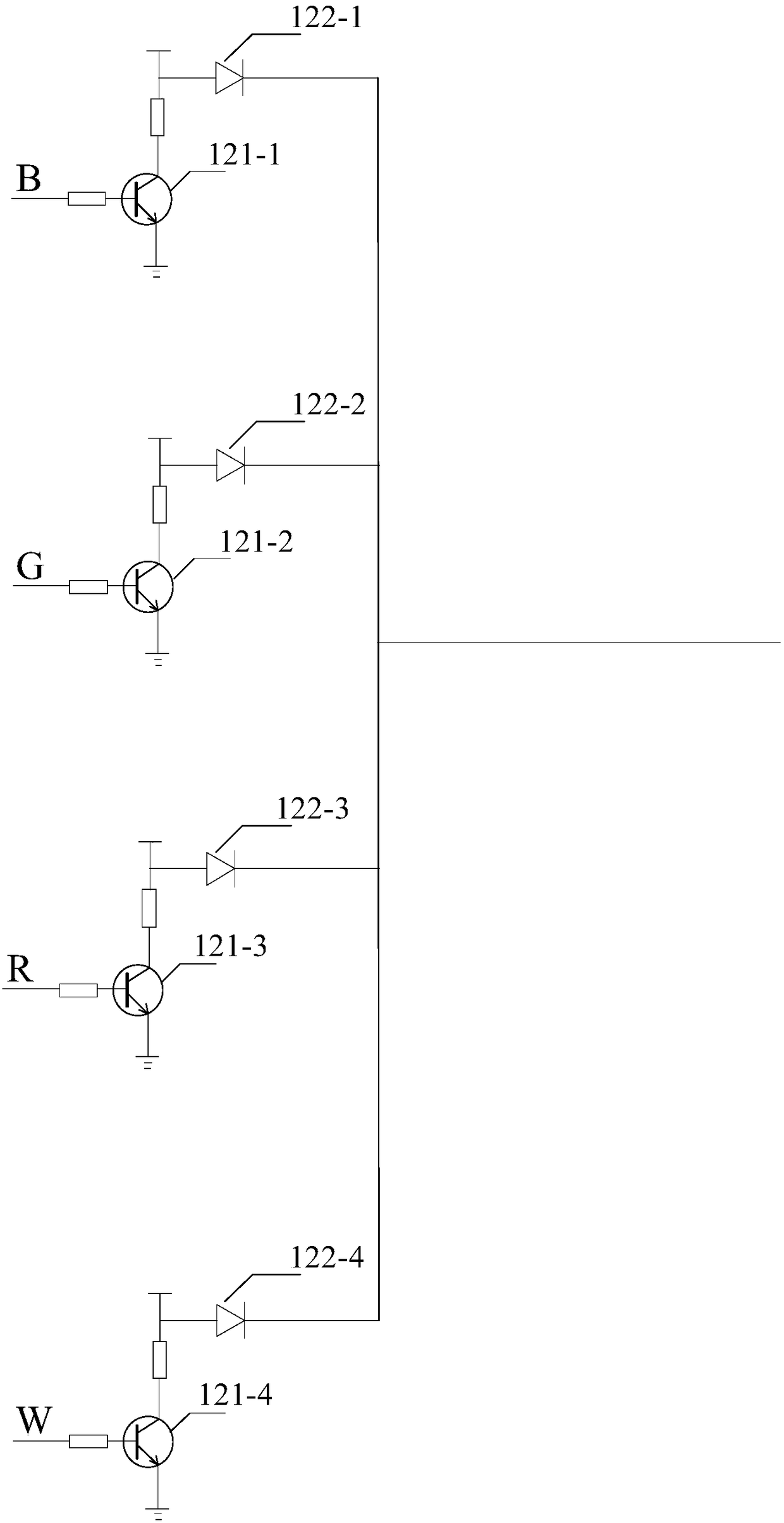
[0060] refer to figure 2 As shown, in one embodiment, the control module 12 includes 4 first triodes and 4 first diodes. The four first triodes are marked with icons 121-1, 121-2, 121-3 and 121-4 respectively, and the four first diodes are marked with icons 122-1, 122-2, 122-3 and 122 respectively -4 logo.

[0061] The connection points identified by the same letter in two or more drawings are the connection points that are connected to each other. figure 1 Connecti...

Embodiment 3

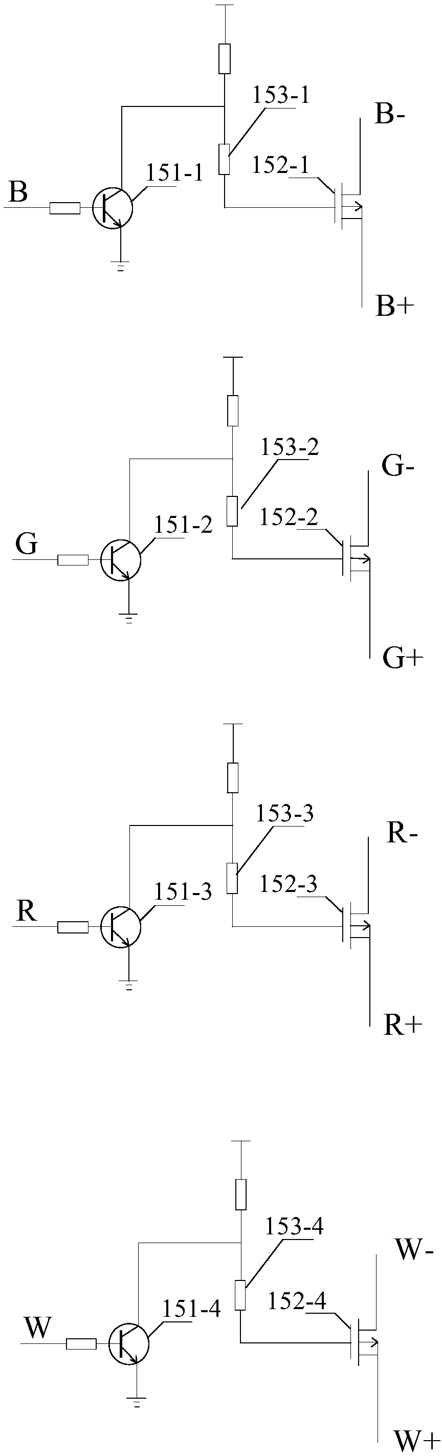
[0074] The control module 12 can have various specific structures, and the third embodiment provides another structure of the control module 12 . refer to Figure 5 As shown, in one embodiment, the control module 12 includes 4 second diodes and a second triode 124. The 4 second diodes are represented by icons 123-1, 123-2, 123-3 respectively. and 123-4 logo. figure 1 Connection point B, connection point G, connection point R, connection point W in the Figure 5 Connect the corresponding connection points one by one.

[0075] The second triode 124 is a PNP type triode, the cathodes of the four second diodes are respectively connected to a PWM signal corresponding to the control signal, and the anodes of the four second diodes are all connected to one end of the first resistor. The other end of a resistor is connected to the base of the second triode 124, the emitter of the second triode 124 is pulled high, the second resistor is connected between the emitter and the base of ...


PUM


Abstract

The invention provides a lamp control circuit and lamp control method. The lamp control circuit comprises a signal module, a control module, a driving module and an adjustment module, wherein the signal module is used for outputting a control signal, the control signal comprises K paths of PWM signals with adjustable duty ratios, K is more than or equal to 2, the control module is used for outputting an enable signal to the driving module when at least one path of PWM signal in the control signal is a trigger level, the driving module is used for driving an LED lamp bead string when the enablesignal is received, the LED lamp bead string comprises K groups of monochromic LED lamp beads with different colors, the adjustment module is used for switching a bright state of a group of monochromic LED lamp beads corresponding to a path of PWM signal when an arbitrary path of PWM signal in the control signal is in high-low conversion. By adjusting the duty ratios of the PWM signals, the LED lamp bead strings can give out monochromic light or hybrid light with various colors and color temperatures.

Description

technical field [0001] The invention relates to the technical field of illumination, in particular to a lamp control circuit and a control method for a lamp. Background technique [0002] The color and color temperature of common LED lights are fixed, which cannot meet the needs of users in various application scenarios. For example, reading lights and decorative lights usually need to be purchased separately, and the same lamp cannot be used as both a reading light and a decorative light. For example, the color temperature of the reading light is around 5000K, while the color temperature of the red color light is around 1500K. Reading lights are used by users almost every day, but decorative lights may only be used on holidays, and most of the other times are idle. Users cannot use a light as a reading light on weekdays and use the same light as a decorative light on holidays. Contents of the invention [0003] (1) Technical problems to be solved [0004] The first ob...

Claims


Application Information

Patent Timeline
Patent Type & Authority Applications(China)
IPC IPC(8): H05B33/08H05B44/00
CPCH05B45/20H05B45/37Y02B20/30
Inventor 孙胜利姜兆宁刘达平孙鹏
Owner BEIJING XIAOMI MOBILE SOFTWARE CO LTD
Why Eureka
Try Eureka