Connection mechanism for crankshaft and flying shear rest

A connecting mechanism and flying scissors technology, which is applied in the field of flying shears, can solve the problems of poor working conditions, high cost, and troublesome replacement of flying shears, and achieve the effects of avoiding direct wear, increasing service life, and good lubrication effect

Pending Publication Date: 2018-10-09
JIANGSU HEFUTE GEAR MFG
View PDF0 Cites 0 Cited by
  • Summary
  • Abstract
  • Description
  • Claims
  • Application Information

AI Technical Summary

Problems solved by technology

[0002] At present, all kinds of crank-type flying shears on the market are connected by the crankshaft and the tool holder. The crankshaft head and the tool holder are in contact through a copper sleeve. The copper sleeve acts as a bearing. The outer circle of the copper sleeve and the inner hole of the tool holder are connected by interference. , the inner hole of the copper sleeve and the outer circle of the crankshaft ha

Method used


Image

  • Connection mechanism for crankshaft and flying shear rest
  • Connection mechanism for crankshaft and flying shear rest

Examples


Example Embodiment

[0014] The technical solutions in the embodiments of the present invention will be described in detail below in conjunction with the accompanying drawings in the embodiments of the present invention. Obviously, the described embodiments are only a part of the embodiments of the present invention, rather than all the embodiments. Based on the embodiments of the present invention, all other embodiments obtained by those of ordinary skill in the art without creative work shall fall within the protection scope of the present invention.

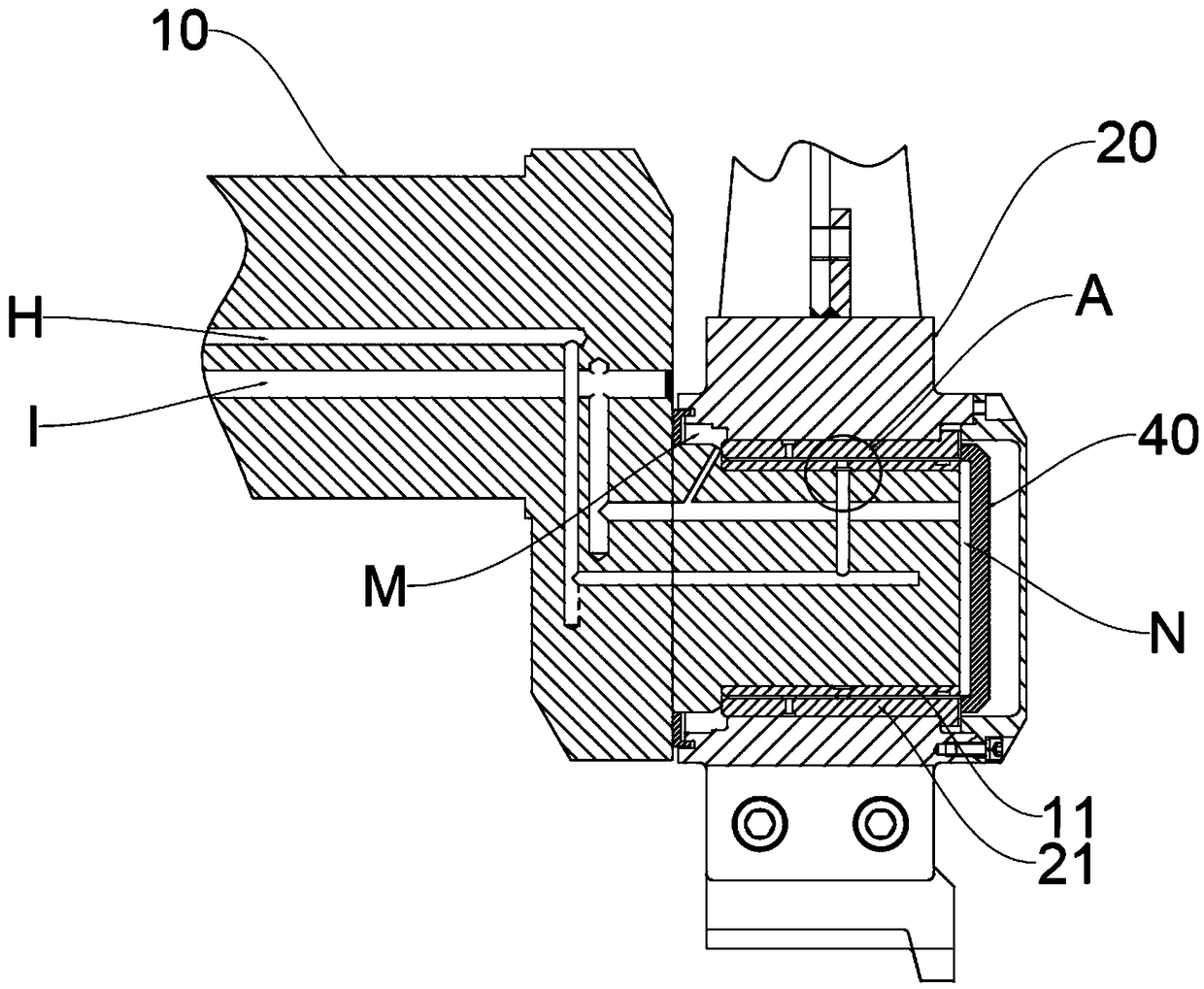
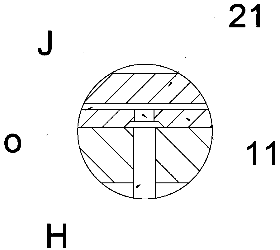
[0015] Reference attachment figure 1 , A connecting mechanism of a crankshaft and a flying scissors frame, comprising a crankshaft 10 and a knife holder 20, the crankshaft has a shaft head, the knife holder has a shaft hole, and the shaft head can be inserted into the shaft hole, A copper sleeve 21 is installed in the shaft hole by interference, and a steel sleeve 11 is provided on the interference sleeve on the shaft head. There is a lubrication gap ...


PUM


Abstract

The invention discloses a connection mechanism for a crankshaft and a flying shear rest. The connection mechanism comprises the crankshaft and the flying shear rest. The crankshaft is provided with ashaft head, the flying shear rest is provided with a shaft hole, the shaft head is rotationally inserted into the shaft hole, a copper sleeve is installed in the shaft hole through interference, the shaft head is sleeved with a steel sleeve through interference, and a lubricating gap is reserved between the steel sleeve and the copper sleeve. Since the steel sleeve is added to the shaft head of the crankshaft, direct abrasion caused to the shaft head in the working process is avoided, the steel sleeve can be replaced after being abraded, replacement is convenient, and the cost is greatly reduced.

Description

Technical field [0001] The invention mainly relates to the technical field of flying shears, in particular to a connecting mechanism of a crankshaft and a flying shear frame. Background technique [0002] At present, all kinds of crank-type flying shears on the market are connected by the crankshaft and the tool holder. The crankshaft head and the tool holder are in contact through a copper sleeve. The copper sleeve acts as a bearing. The outer circle of the copper sleeve and the inner hole of the tool holder are connected by interference , The inner hole of the copper sleeve and the outer circle of the crankshaft are in a clearance fit, and the gap is filled with grease lubrication, but the flying shear site is poor, the temperature is higher, and the grease is prone to failure. Later, the crankshaft needs to be removed and replaced as a whole, which is troublesome and costly. Summary of the invention [0003] In view of the shortcomings of the prior art, the present invention p...

Claims


Application Information

Patent Timeline
IPC IPC(8): B23D25/06B23D35/00
CPCB23D35/002B23D25/06
Inventor 宋廷钱江王福龙
Owner JIANGSU HEFUTE GEAR MFG
Why Eureka
Try Eureka