Multi-main-shaft vertical machining center

A vertical machining center, multi-spindle technology, applied in metal processing, metal processing equipment, manufacturing tools, etc., can solve the problems of affecting work efficiency, restricting productivity, and the large area of ​​​​the machining center, reducing vibration and mutual interference, The effect of improving machining accuracy and reducing tool wear

Pending Publication Date: 2018-10-09
林志贺
View PDF1 Cites 2 Cited by
  • Summary
  • Abstract
  • Description
  • Claims
  • Application Information

AI Technical Summary

Problems solved by technology

Conventional processing centers occupy a large area, and workers have to walk more distances when operating multiple machines, which increases the labor intensity of workers and affects work efficiency; in addition, with the shrinking of land resources, the cost of processing sites is getting higher and higher, so It is hoped that the equipment can be more compact and miniaturized, so as to increase the volume ratio of the workshop and reduce management costs
At present, the machining centers on the market are basically single-spindle structures, which are relatively inefficient for large-scale processing of some small and medium-sized parts, because only one tool is involved in processing at the same time.
However, although the combination machine tool can participate in the cutting with multiple spindles at the same time and improve the efficiency, its versatility is poor, and adjustment and maintenance are also troublesome.
A Chinese patent discloses a gantry multi-axis machining center (patent number: 201120550910.9). Although it adopts a multi-spindle structure, its tools cannot be automatically replaced, thus restricting productivity
At present, some gantry machining centers on the market adopt a double-spindle structure, but they cannot perform independent compensation for the tool length of the two spindles, which affects the scope of use of the equipment.

Method used


Image

  • Multi-main-shaft vertical machining center
  • Multi-main-shaft vertical machining center
  • Multi-main-shaft vertical machining center

Examples


Embodiment Construction

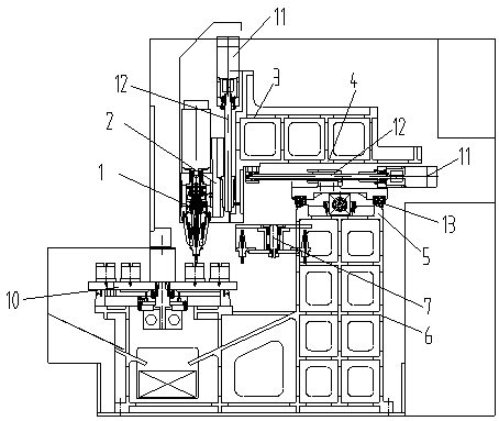
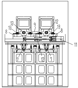
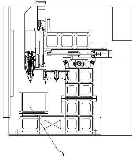
[0018] refer to figure 1 , 2 In the first embodiment shown, in this embodiment, the spindle unit, the X-direction CNC slide table, the Y-direction CNC slide table, the Z-direction CNC slide table, and the rotary tool magazine all adopt two groups; On the slide plate 2 of the Z-direction CNC slide table; the base 3 of the Z-direction CNC slide table and the base 4 of the Y-direction CNC slide table are manufactured as one, and the Z-direction CNC slide table and the Y-direction CNC slide table form a vertical T-shaped structure layout The base 5 and the body 6 of the X-direction CNC slide table are manufactured as one; two sets of direct-connected spindle units 1 are arranged side by side in parallel, and a servo rotary tool magazine 7 is installed on the lower body 6 of each direct-connected spindle unit 1; The slide plates 8 of the two sets of X-direction CNC slide tables are fixedly connected together through the connecting plate 9; the two sets of Y-direction CNC slide tab...


PUM


Abstract

The invention discloses a multi-main-shaft vertical machining center. The center is mainly composed of a plurality of sets of main shaft units, X-direction numerical control sliding tables, Y-direction numerical control sliding tables, Z-direction numerical control sliding tables, rotary tool changers and a set of machine body. According to the machining center, multi-main-shaft synchronous tool changing can be carried out at the same time, and independent compensation can be independently carried out on the length of the tool on each main shaft; and the multi-main-shaft vertical machining center is simple in structure and convenient to maintain, and is ideal drilling and milling comprehensive machining equipment.

Description

technical field [0001] The invention relates to a vertical machining center, in particular to a multi-spindle vertical machining center. Background technique [0002] With the revitalization and development of the national equipment manufacturing industry, CNC machine tools, as the mainstream product of the machine tool industry, have become the key equipment to realize the modernization of the equipment manufacturing industry. Conventional processing centers occupy a large area, and workers have to walk more distances when operating multiple machines, which increases the labor intensity of workers and affects work efficiency; in addition, with the shrinking of land resources, the cost of processing sites is getting higher and higher, so It is hoped that the equipment can be more compact and miniaturized, so as to increase the volume ratio of the workshop and reduce management costs. At present, the machining centers on the market are basically single-spindle structures, wh...

Claims


Application Information

Patent Timeline
Patent Type & Authority Applications(China)
IPC IPC(8): B23Q37/00
CPCB23Q37/00
Inventor 林志贺
Owner 林志贺
Why Eureka
Try Eureka