Half-wavelength Transmission Line Fault Location Method Considering Traveling Wave Velocity Variation and Arrival Time Compensation

A technology of arrival time and transmission line, applied in fault location, fault detection according to conductor type, measurement of electricity, etc., can solve the problem of large fault location error of half-wavelength transmission line, and achieve high engineering practical significance, high precision and adaptability. good effect

Active Publication Date: 2019-05-14
CHINA UNIV OF MINING & TECH
View PDF7 Cites 0 Cited by
  • Summary
  • Abstract
  • Description
  • Claims
  • Application Information

AI Technical Summary

Problems solved by technology

[0004] In order to solve the problem of large errors in fault location of half-wavelength transmission lines in the current traveling wave method, the purpose of this invention is to propose a half-wavelength transmission line fault location method that considers the change of traveling wave velocity and the compensation of arrival time

Method used


Image

  • Half-wavelength Transmission Line Fault Location Method Considering Traveling Wave Velocity Variation and Arrival Time Compensation
  • Half-wavelength Transmission Line Fault Location Method Considering Traveling Wave Velocity Variation and Arrival Time Compensation
  • Half-wavelength Transmission Line Fault Location Method Considering Traveling Wave Velocity Variation and Arrival Time Compensation

Examples


Embodiment Construction

[0023] The present invention will be further described below in conjunction with the accompanying drawings.

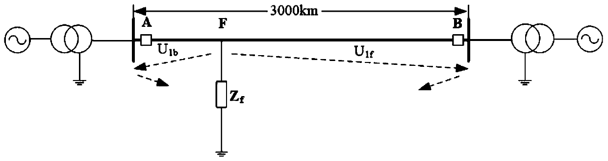
[0024] Half-wavelength transmission lines such as figure 1 As shown, where the first point A and the end point B are the measurement points at the first and last ends of the transmission line respectively, point F is the fault point, and point Z f is the fault resistance, U 1b and U 1f are the initial traveling waves of the reverse and forward line-mode voltages, respectively. The dotted arrow in the figure indicates the direction of initial traveling wave propagation.

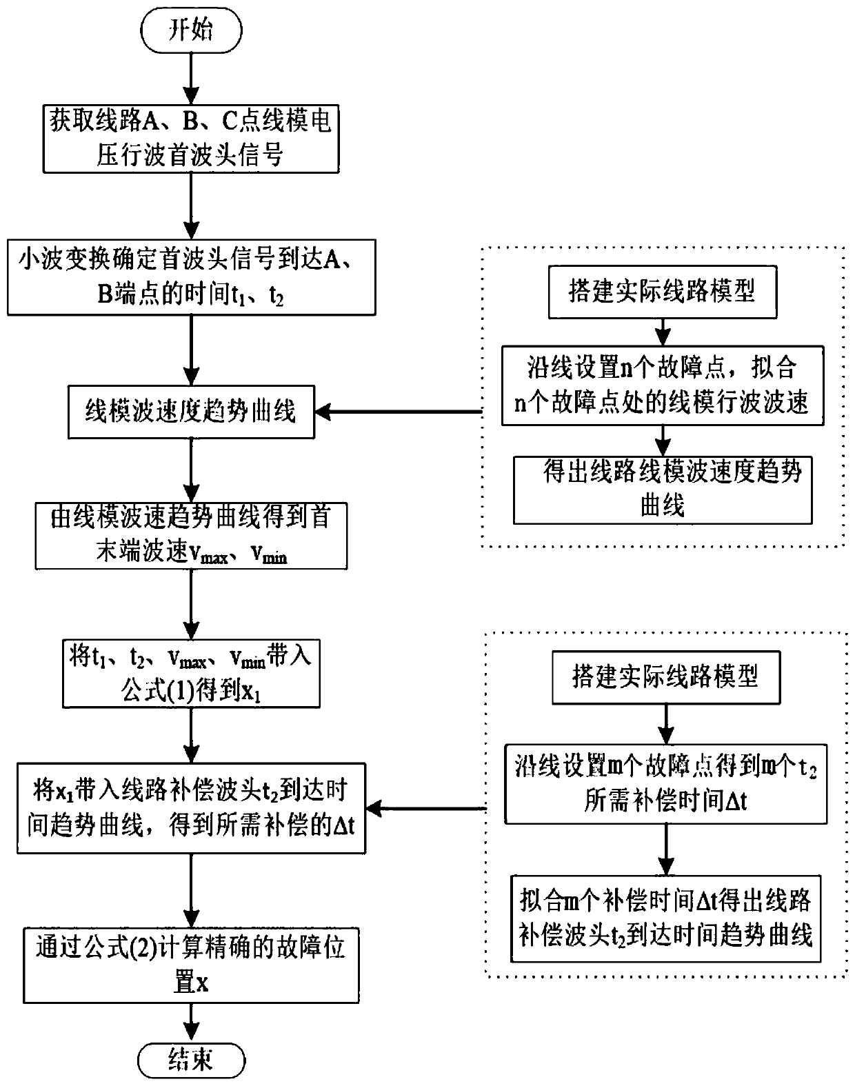
[0025] The half-wavelength transmission line fault location method of the present invention, which considers the change of traveling wave velocity and the compensation of arrival time, comprises the following steps:

[0026] (1) Point A at the head end and point B at the end represent the measurement points at both ends of the half-wavelength transmission line, and point F represents the fault poin...


PUM


Abstract

The invention discloses a half-wavelength transmission line fault ranging method considering traveling wave speed change and arrival time compensation. The frequency-dependent characteristics of the line make the attenuation and dispersion of different frequency components of the traveling wave head different, and the wave velocity presents an attenuation trend. According to the relationship between the linear mode wave velocity and the fault location, the double-terminal synchronous measurement is used to consider the range of wave velocity variation, and the maximum and minimum wave velocity along the line are brought into the formula to obtain the preliminary fault distance. The curve fitting is used to correct the arrival time of the linear model traveling wave head calculated by the fault remote measuring point, and the final fault distance is obtained. Compared with the traditional double-terminal traveling wave ranging, the invention has higher ranging accuracy, good adaptability, and good engineering practice value.

Description

technical field [0001] The invention relates to a half-wavelength transmission line fault ranging method based on traveling wave speed change and arrival time compensation. Background technique [0002] Half-wavelength AC transmission Half-wavelength AC transmission is an ultra-long-distance AC transmission method. Compared with conventional AC transmission, it has the advantages of no need to install reactive power compensation equipment, strong transmission capacity, and good economy. The half-wavelength power transmission distance is long, and the line spans a wide range of regions, so it is very easy to fail due to internal and external factors. If the fault cannot be cleared in time, it will seriously affect the safe and stable operation of the system. [0003] At present, there are mainly single-ended and double-ended methods for distance measurement of transmission line traveling waves. The single-ended method does not require synchronization, but needs to detect the...

Claims


Application Information

Patent Timeline
Patent Type & Authority Patents(China)
IPC IPC(8): G01R31/08
CPCG01R31/085G01R31/088
Inventor 梁睿彭楠孟祥震周鲁天杨智
Owner CHINA UNIV OF MINING & TECH
Why Eureka
Try Eureka