
Insulated hemostatic clip

A technology of hemostatic clip and layer insulation, which is applied in the field of medical devices, can solve problems such as electrical damage, and achieve the effect of avoiding electrical damage to digestive tract tissues

Pending Publication Date: 2018-10-12
唐丹
View PDF3 Cites 3 Cited by
  • Summary
  • Abstract
  • Description
  • Claims
  • Application Information

AI Technical Summary

Problems solved by technology

[0003] The purpose of the present invention is to provide an insulating hemostatic clip, which is used to solve the problem that the existing hemostatic clip is likely to cause electrical damage when it is treated with a high-frequency electric knife and an electric snare.

Method used


Image

  • Insulated hemostatic clip
  • Insulated hemostatic clip
  • Insulated hemostatic clip

Examples


Embodiment 1

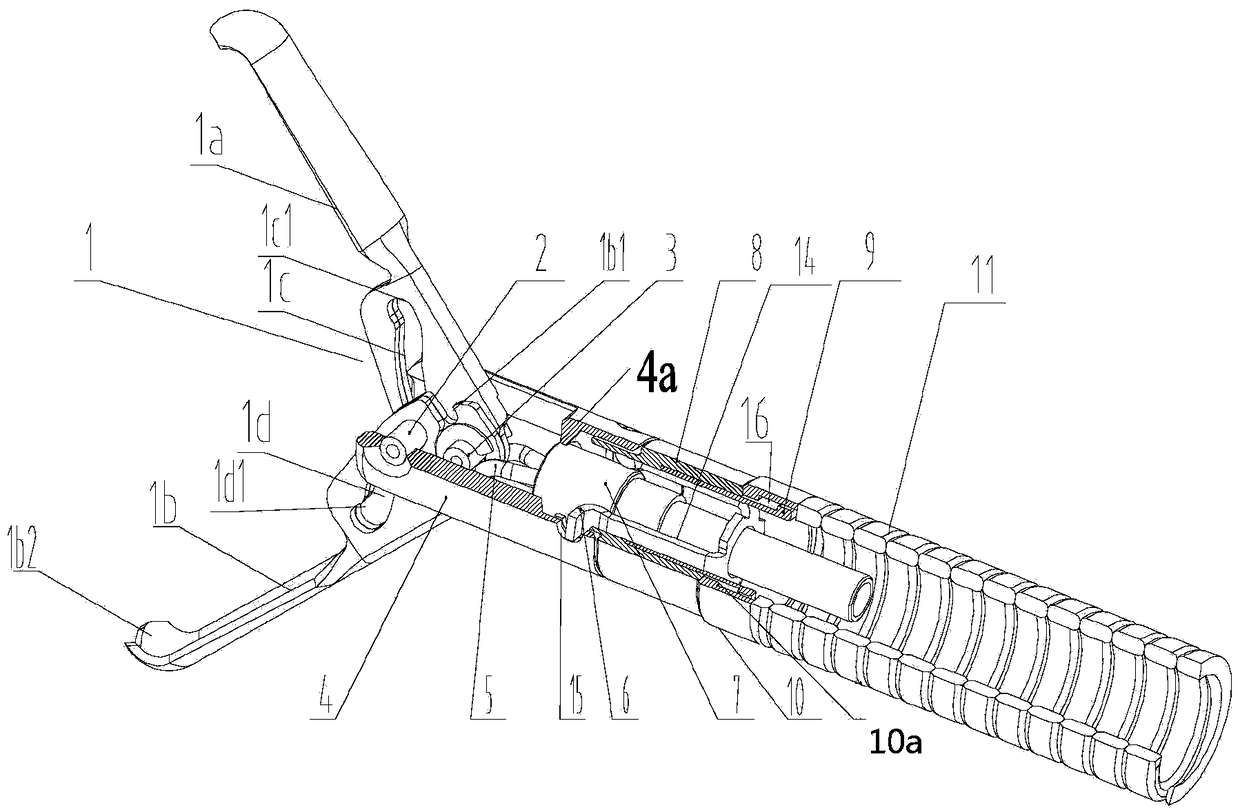
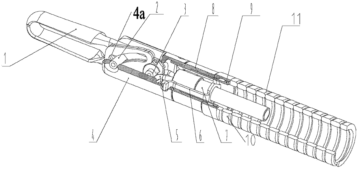
[0026] Such as figure 1 with figure 2 As shown, the present invention discloses an insulating hemostatic clip. The insulating hemostatic clip includes an outer sleeve assembly and a clamping device located in the outer sleeve assembly. The outer sleeve assembly includes a fixed seat 4, a transition cap 8, and a fixed The cap 10 and the distal spring tube 11, the clamping device includes a clip body 1, a wire buckle 5, a connecting piece 7, and an operating rope 14 connected to an operating handle 13, which are sequentially connected; a fixed pin 2 is provided at the front end of the fixing seat, The clip body 1 is composed of two clamping arms 1a, 1b, the tail ends of the two clamping arms 1a, 1b are connected by a movable pin 3, and the middle of the two clamping arms 1a, 1b is provided with a sliding groove 1c, 1d, the occlusal distal ends of the two clamping arms 1a, 1b are in a zigzag 1b2 fit. Such as Figure 8 As shown, the outer surfaces of the two clamping arms 1a, 1b a...

Embodiment 2

[0036] Such as Picture 9 As shown, this embodiment is based on embodiment 1. The difference between this embodiment and embodiment 1 is that the inner surfaces of the clamping arms 1a, 1b are also covered with multiple layers of silica gel 18. The number of layers of silica gel 18 and the clamping The number of layers of silica gel 18 on the outer surfaces of the arms 1a and 1b is the same.

Embodiment 3

[0038] This embodiment is based on embodiment 2. The difference between this embodiment and embodiment 2 is that the outer peripheral surface of the fixing seat 4 is also covered with multiple layers of silica gel 18, the number of layers of silica gel 18 and the inner surfaces of the clamping arms 1a, 1b The number of layers of silica gel 18 is the same. Further, in order to improve the insulation performance, the outer peripheral surface of the transition cap 8 can also be covered with multiple layers of silica gel 18.


PUM


Abstract

The invention relates to an insulated hemostatic clip. The insulated hemostatic clip comprises a clamping device and a fixed base. The clamping device comprises a clip body and a wire buckle connectedin sequence. The front end of the fixed base is provided with a fixed pin. The clip body is formed by two clamping arms, the tail ends of the two clamping arms are connected by a movable pin, and themiddles of the two clamping arms are respectively provided with a sliding slot, and the fixed pin penetrates the sliding slots. The two clamping arms reciprocate along the sliding slots to form opening and closing of the clip body. The outer surfaces of the two clamping arms are covered with at least one insulating material layer. By means of the fact that the outer surfaces of the two clamping arms are covered with insulating materials, the metal hemostatic clip and an endotherm knife or an electric snare are isolated by the insulating materials, and electric injury to digestive tract issuescaused by the fact that current is led into the metal hemostatic clip when the metal hemostatic clip and the endotherm knife contact is avoided.

Description

Technical field [0001] The present invention relates to the technical field of medical devices, in particular to an insulating hemostatic clip. Background technique [0002] In recent years, endoscopic hemostatic clips have become the most effective non-surgical treatment for acute gastrointestinal bleeding in critically ill patients and have the most clinical application value due to their characteristics such as low trauma, fast hemostasis, low incidence of rebleeding, few complications, and definite curative effect. Methods. The effect of the hemostatic clip for clamping small blood vessels and hemostasis has been recognized. However, after the hemostatic clip clamps the wound, if there is still a small amount of bleeding around, and because it is close to the previous metal clip, the new hemostatic clip is usually not used. High-frequency electrosurgical coagulation is used to stop the bleeding, but the electrosurgical can not avoid contact with the previous metal clip. At t...

Claims


Application Information

Patent Timeline
IPC IPC(8): A61B17/122A61B17/00
CPCA61B17/00234A61B17/122A61B2017/00929A61B2017/12004
Inventor 唐丹令狐恩强
Owner 唐丹
Learn More