Air-injection type lacrimal stent supporting device

An air injection and lacrimal duct technology, which is applied in the field of medical devices, can solve the problems that patients cannot operate at home, complicated lacrimal duct operation, chronic inflammatory response, etc., and achieve the effect of simple structure, reducing tissue damage and reducing inflammation

Pending Publication Date: 2018-10-12
SHANGHAI TONGJI HOSPITAL
View PDF10 Cites 2 Cited by
  • Summary
  • Abstract
  • Description
  • Claims
  • Application Information

AI Technical Summary

Problems solved by technology

[0004] The existing lacrimal duct stents have the following deficiencies: 1. The existing lacrimal duct stents are complicated to flush the lacrimal ducts or administer medicines, and often need to go to the hospital for treatment, and patients cannot operate at home
2. Existing stents generally have a constant diameter and cannot expand the lacrimal duct, which can easily cause chronic inflammatory reactions and cause lacrimal duct obstruction again after extubation
However, there is no corresponding disclosure about a lacrimal duct stent with an adjustable tube diameter, which can exercise the sphincter function of the lacrimal duct through dilation, and is convenient for doctors and patients to use.
[0007] To sum up, there is an urgent need for an adjustable stent that can exercise the sphincter function of the lacrimal duct through expansion, and is convenient for doctors and patients to use. Patients can visually wash the lacrimal duct stent for dressing change operations by themselves. This lacrimal duct stent has not been reported yet

Method used


Image

  • Air-injection type lacrimal stent supporting device
  • Air-injection type lacrimal stent supporting device
  • Air-injection type lacrimal stent supporting device

Examples


Embodiment Construction

[0032] The present invention will be further described below in conjunction with embodiments and with reference to the drawings.

[0033] The reference numerals and components involved in the drawings are as follows:

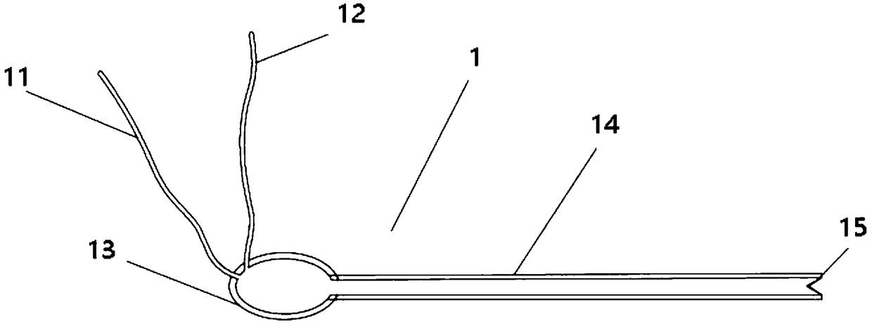
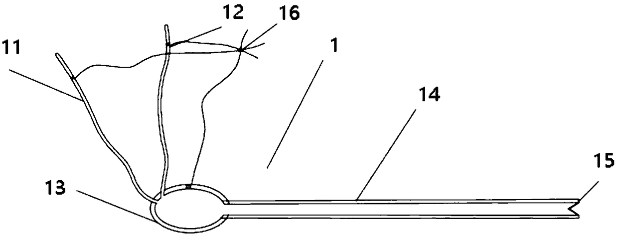
[0034] 1. Lacrimal stent

[0035] 11. Upper lacrimal canaliculus

[0036] 12. Lacrimal canaliculus

[0037] 13. Lacrimal sac

[0038] 14. Nasolacrimal duct

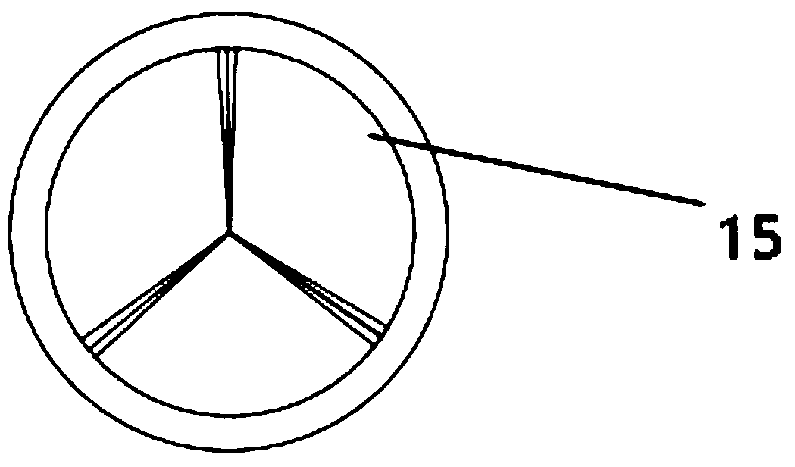
[0039] 15. Gas injection port

[0040] 16.Guide line

[0041] 2. Gas injection needle

[0042] 21. Gas injection needle body

[0043] 22. Inflator

[0044] 23. LED lights

[0045] 24. Piston

[0046] 25. LED light switch

[0047] Please refer to figure 1 , figure 1 It is a schematic structural diagram of a supporting device of an air-injected lacrimal duct stent 1 of the present invention. A supporting device for an air-injected lacrimal duct stent 1. The supporting device of the lacrimal duct stent 1 includes a lacrimal duct stent 1 and an air injection needle 2; the lacrimal duct stent 1 includes an upper lacrimal canalicul...


PUM


Abstract

The invention relates to an air-injection type lacrimal stent supporting device. The lacrimal stent supporting device comprises a lacrimal stent and an air-injection needle. The lacrimal stent comprises an upper lacrimal ductule part, a lower lacrimal ductule part, a lacrimal sac part, a nasolacrimal duct part and an air-injection hole; the upper lacrimal ductule part and the lower lacrimal ductule part are both of a hollow structure and are communicated with the lacrimal sac part; the lacrimal sac part is communicated with the nasolacrimal duct part; one end of the nasolacrimal duct part is communicated with the lacrimal sac part, and the air-injection hole is formed in the other end of the nasolacrimal duct part. The air-injection needle comprises an air-injection needle body, an air-injection cylinder, an LED lamp, a piston and an LED lamp switch. The air-injection type lacrimal stent supporting device has the advantages that by adjusting the thickness of the stent, inflammatory substances in a lacrimal passage are helped to be washed, and the functions of the sphincter of the lacrimal passage are exercised; the operation is simple and convenient, a patient can operate the supporting device by himself/herself at home, the medical cost is greatly reduced, the epiphora state of the patient can be better improved, the life quality of the patient is improved, and meanwhile, therecurrence rate of obstruction of the lacrimal passage is reduced.

Description

Technical field [0001] The present invention relates to the technical field of medical devices, in particular to a supporting device for a gas injection type lacrimal duct stent. Background technique [0002] Lacrimal obstruction is a common lacrimal disease in ophthalmology, often causing clinical symptoms of tearing, which can seriously affect the quality of life of patients. Lacrimal obstructive diseases mostly occur in adult women and middle-aged and elderly people. The common causes are inflammation, trauma, and stones in the lacrimal duct. Epilepsy often leads to flushing and erosion of the skin of the lacrimal sac, causing imbalance of the ocular surface flora. If not treated in time, it is easy to form dacryocystitis and ocular surface diseases. [0003] The treatment method is mostly lacrimal duct placement. Lacrimal duct placement refers to the placement of a lacrimal duct drainage tube on the site of the lacrimal duct obstruction. It is mainly used for the treatment of...

Claims


Application Information

Patent Timeline
Patent Type & Authority Applications(China)
IPC IPC(8): A61F2/82A61F9/007
CPCA61F2/82A61F9/00736
Inventor 毕燕龙张娟郑昌月牛国桢
Owner SHANGHAI TONGJI HOSPITAL
Why Eureka
Try Eureka