An intelligent assembly robot for power distribution cabinet

A power distribution cabinet and robot technology, applied in the direction of metal processing equipment, metal processing, manufacturing tools, etc., can solve the problems of high labor intensity, easy twisting, cumbersome and complicated process, etc., to reduce labor intensity, improve work efficiency, Simple to use effects

Active Publication Date: 2019-12-13
中通服节能技术服务有限公司
View PDF6 Cites 0 Cited by
  • Summary
  • Abstract
  • Description
  • Claims
  • Application Information

AI Technical Summary

Problems solved by technology

[0003] In order to solve the above problems, the present invention provides an intelligent assembly robot for electric power distribution cabinets, which can solve the problem that when installing screws in the existing power distribution cabinets, it is necessary to use a corresponding screwdriver to work. After taking the screw, use tools to install the screw. Because the screw is small, the screw may fall off during manual installation, and it is easy to twist. When installing cross-recessed and slotted screws, personnel need to use corresponding tools to tighten them. The tool makes it inconvenient for personnel to carry, the process takes a long time, labor intensity is high, and the efficiency is low. It can realize the multi-directional limit function of cross-recessed screws and slotted screws, and automatically switch the corresponding screwdriver according to different screw heads. head, no need for manual installation, no screw falling or twisting, short time-consuming, and has the advantages of simple operation, low labor intensity and high work efficiency

Method used


Image

  • An intelligent assembly robot for power distribution cabinet
  • An intelligent assembly robot for power distribution cabinet
  • An intelligent assembly robot for power distribution cabinet

Examples


Embodiment Construction

[0026] In order to make the technical means, creative features, goals and effects achieved by the present invention easy to understand, the present invention will be further described below in conjunction with specific illustrations. It should be noted that, in the case of no conflict, the embodiments in the present application and the features in the embodiments can be combined with each other.

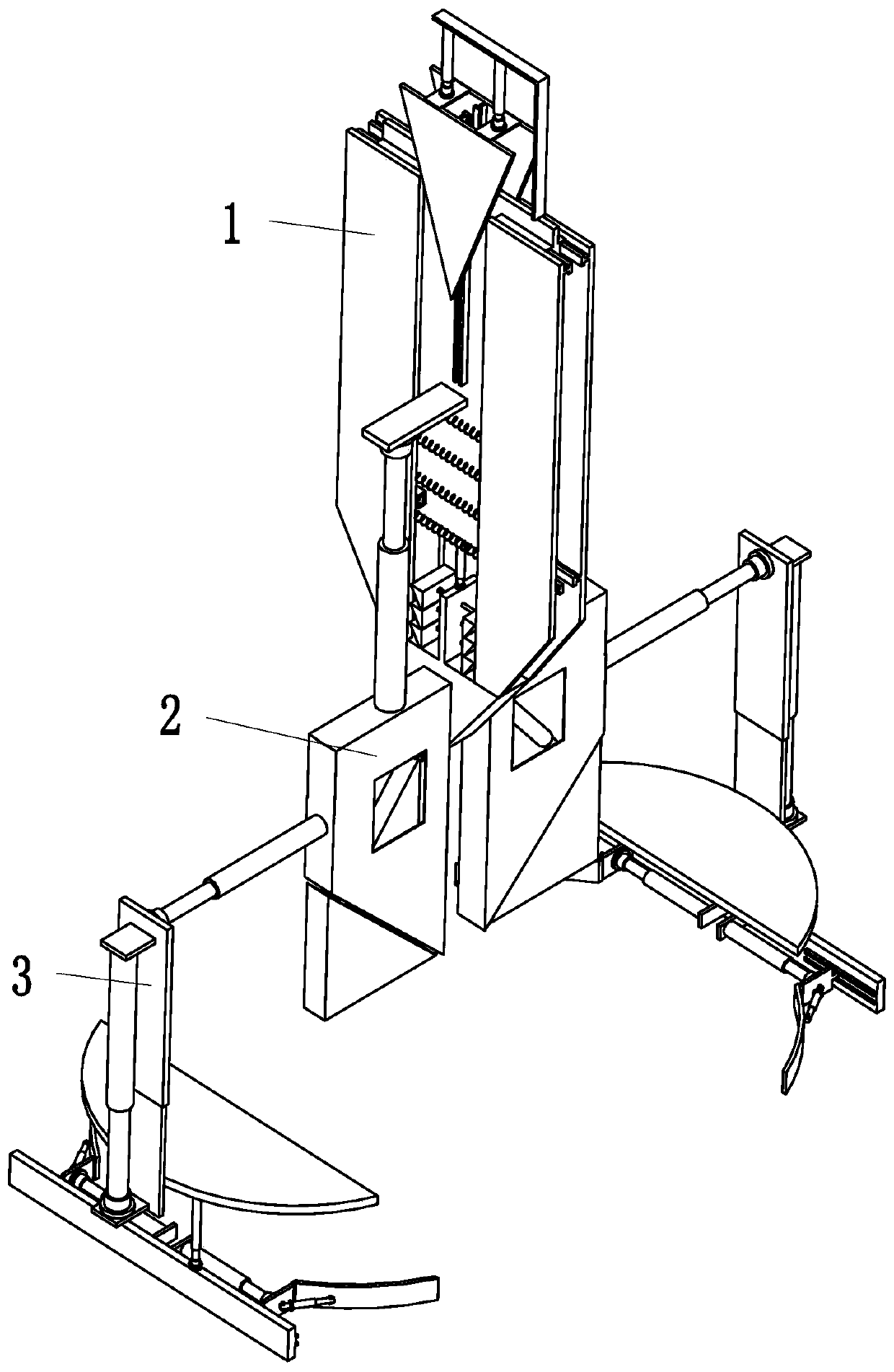
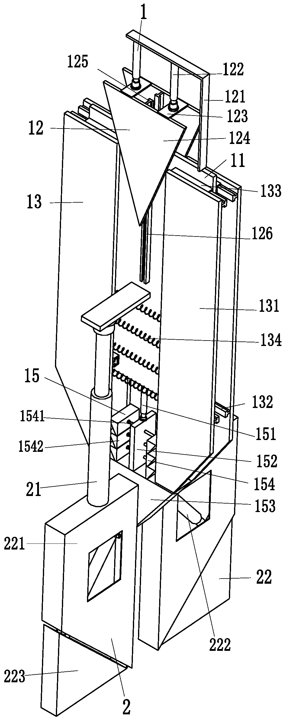
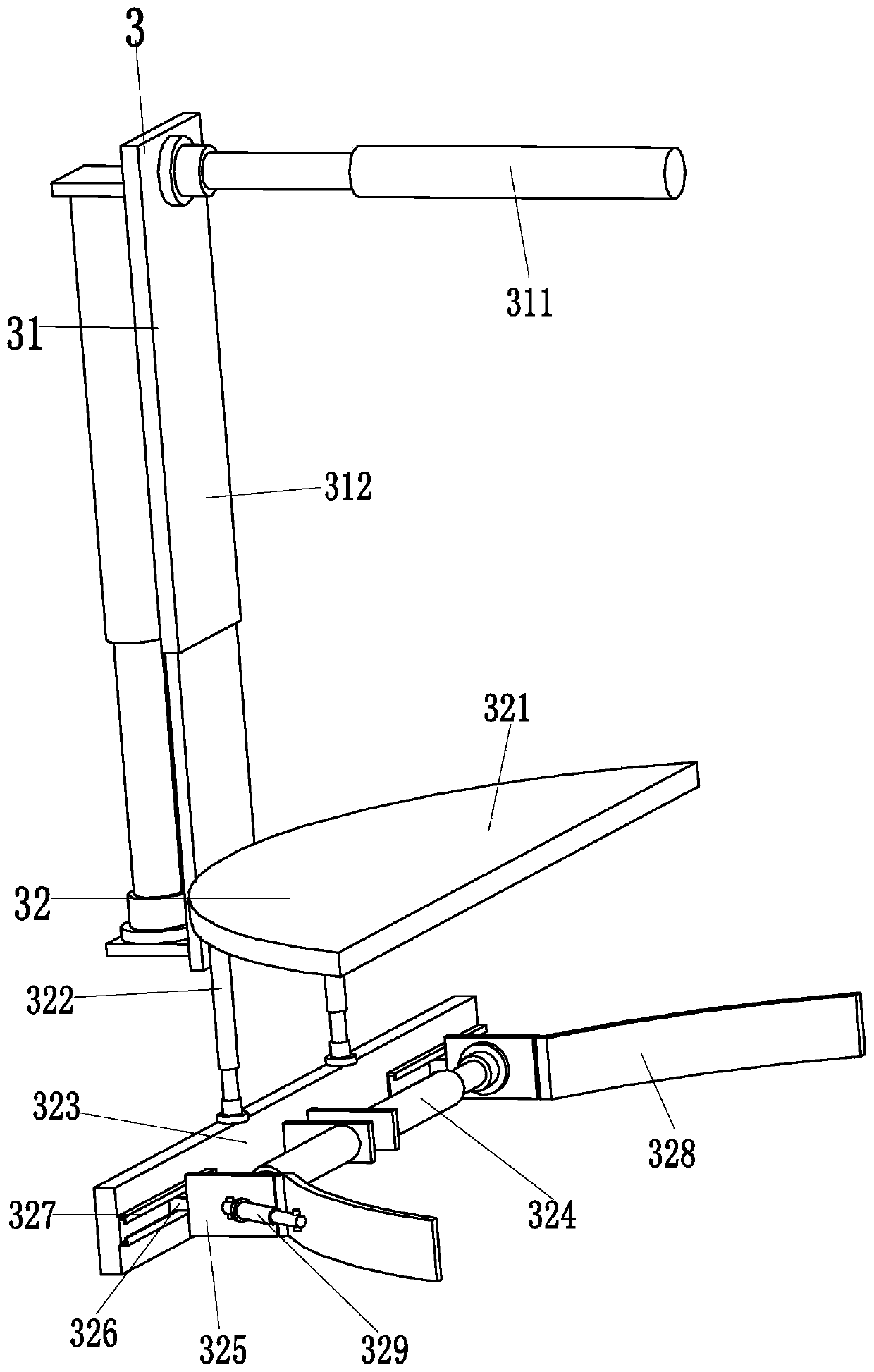
[0027] Such as Figure 1 to Figure 3 As shown, in order to achieve the above purpose, the present invention adopts the following technical solutions: an intelligent assembly robot for power distribution cabinets, including a switching device 1, two slotted devices 2 and two screw head limiting devices 3, the described Two slotted devices 2 are installed in the middle of the switching device 1 , and the two slotted devices 2 are symmetrically arranged, and a screw head limiting device 3 is installed at the outer end of each slotted device 2 .

[0028] The switching device 1 includes ...


PUM


Abstract

The invention relates to an intelligent assembling robot of a power distribution cabinet. The intelligent assembling robot comprises a switching device, two linear groove devices and two screw head limiting devices, wherein the middle of the switching device is provided with the two linear groove devices, the two linear groove devices are symmetrically arranged, and one screw head limiting deviceis installed at the outer end of each linear groove device correspondingly. According to the robot, the problems that when a screw is installed on the power distribution cabinet, a corresponding screwdriver needs to be used for working; when the screw is installed, the screw is required to be held by a person, and then the screw is installed by means of a tool, due to the fact that the screw is small, the screw can fall off during manual installation, and the screw is prone to be twisted in an inclined manner; and when a cross slot screw and a linear groove are installed, the person needs to tighten the cross slot screw and the linear groove by means of the corresponding tool, a large number of tools enable the person to be inconvenient to carry, the process is long in consumed time, laborintensity is high, efficiency is low and the like are solved, so that the function of carrying out multi-azimuth limiting on the cross slot screw and the linear groove screw can be realized.

Description

technical field [0001] The invention relates to the field of installation of electric power distribution cabinets, in particular to an intelligent assembly robot for electric power distribution cabinets. Background technique [0002] The power distribution cabinet (box) is divided into power distribution cabinet (box), lighting distribution cabinet (box), metering cabinet (box), and is the final equipment of the power distribution system. The cabinet is used in the occasions where the load is relatively scattered and there are few circuits. The motor control center is used in the occasions where the load is concentrated and there are many circuits. They distribute the electric energy of a certain circuit of the upper-level power distribution equipment to the nearby load. The load provides protection, monitoring and control. The structure of the distribution box is divided into two types, one is a welded structure, and the other is an assembled structure. The assembled struct...

Claims


Application Information

Patent Timeline
Patent Type & Authority Patents(China)
IPC IPC(8): B23P19/06
CPCB23P19/06
Inventor 张晓锋
Owner 中通服节能技术服务有限公司
Why Eureka
Try Eureka