Eureka AIR delivers breakthrough ideas for toughest innovation challenges, trusted by R&D personnel around the world.

Flexible clamping jaw

A gripper and flexible technology, applied in the field of flexible grippers, can solve the problems of inability to meet the adaptive grasping of objects of different shapes and sizes, reduce production efficiency and income, damage the surface of items, etc., to achieve a wide range of applications and increase production efficiency. And the effect of high income and high grasping stability

Inactive Publication Date: 2018-10-12
SUZHOU QIAOYUE SOFTWARE
View PDF7 Cites 10 Cited by
  • Summary
  • Abstract
  • Description
  • Claims
  • Application Information

AI Technical Summary

Problems solved by technology

[0002] In the workshop, sometimes it is necessary to clamp the product or article with the jaws, and at the same time position the product or article on the main shaft of the lathe or the moving work platform, and the product or article needs to rotate together with the main shaft of the lathe or the moving work platform, the existing In the technology, the jaws are generally driven by the cylinder to pick up the product. The jaws are designed according to the shape of the product. There are many different jaws in this design, and the jaws of the prior art cannot be used universally, and cannot meet the requirements for objects of different shapes and sizes. It is suitable for grasping, and when grasping fragile or easily scratched items, the surface of the item will be damaged; and the existing technology needs to disassemble the jaws frequently according to different products, the labor intensity of the workers is high, and the flexibility is poor, which also increases Reduced production costs, reduced production efficiency and revenue

Method used


Image

  • Flexible clamping jaw
  • Flexible clamping jaw
  • Flexible clamping jaw

Examples


Embodiment Construction

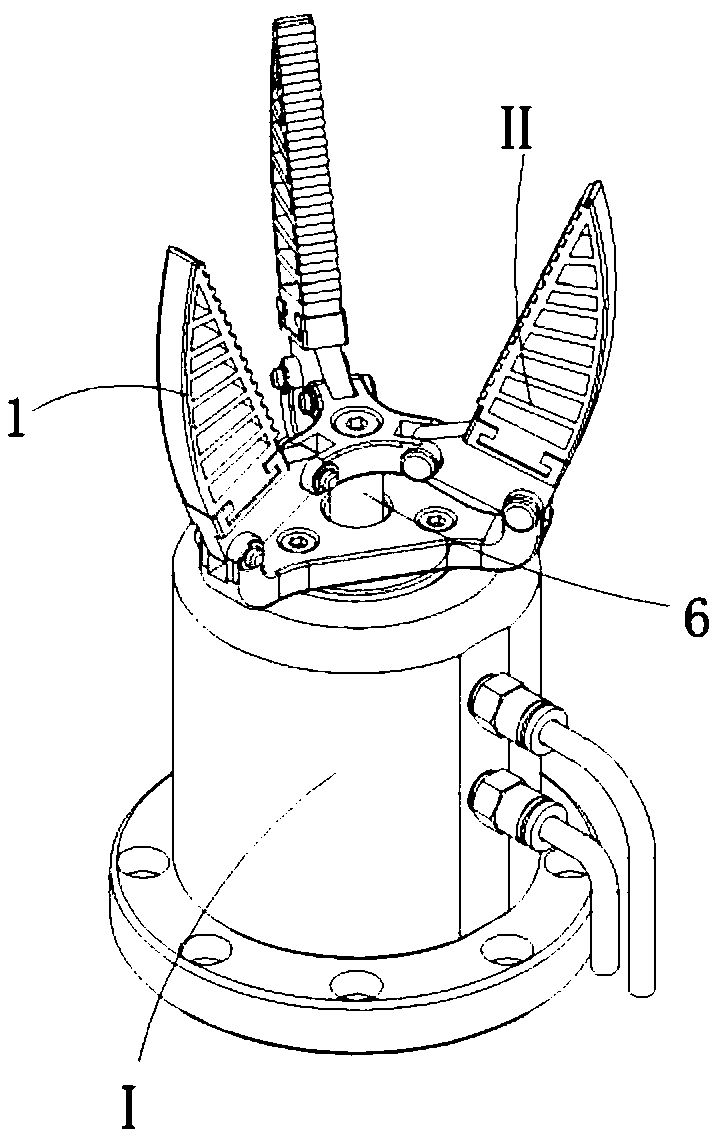
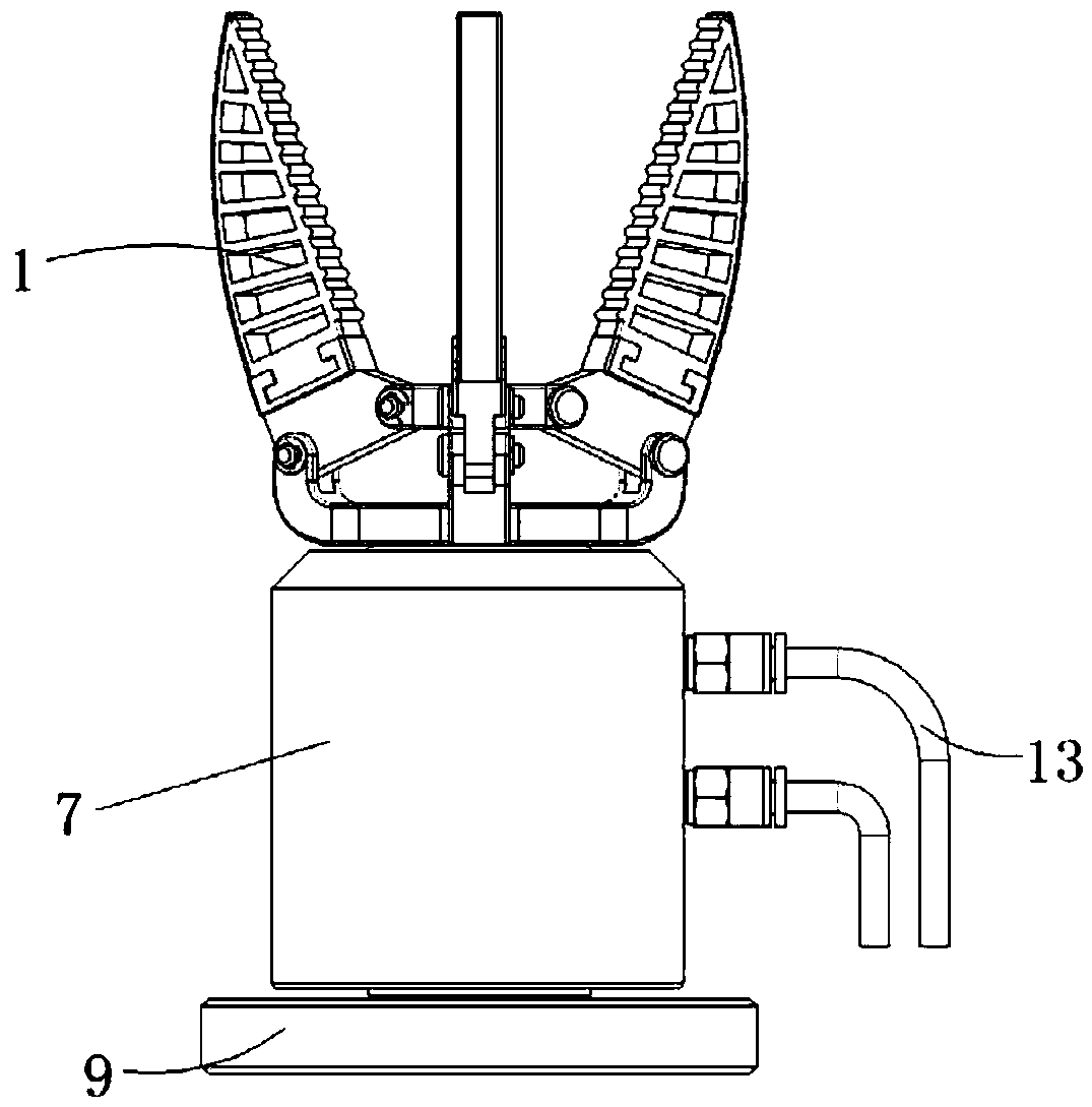
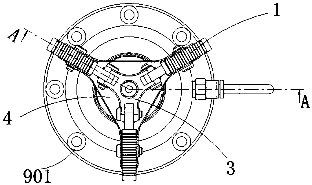
[0026] Examples, see attached Figure 1~6 , a flexible jaw, including a cylinder driving mechanism I and a jaw assembly II movably mounted on the cylinder driving mechanism; the cylinder driving mechanism includes a cylinder 5 and a cylinder rotatably mounted on the periphery The air guide ring 7, the bottom of the cylinder block is connected with a fixed base plate 9, the fixed base plate 9 is a cylindrical plate, and the circumference of the cylindrical plate is provided with eight groups of mounting holes 901, through which the mounting holes can be fixed by using bolts. The base plate is fixed on the main shaft of the lathe or the moving working platform. When the main shaft of the lathe or the moving working platform rotates, the fixed bottom plate will drive the cylinder body to rotate infinitely at 360°, but the air guide ring will not rotate with it, and the air intake pipe or oil pipe installed on the air guide ring will always remain original. status.

[0027] A pi...


PUM


Abstract

The invention relates to a flexible clamping jaw comprising a cylinder driving mechanism and a clamping jaw assembly movably arranged on the cylinder driving mechanism. The cylinder driving mechanismcomprises a cylinder body and a gas guide ring rotationally arranged on the periphery of the cylinder body. A piston is arranged in the cylinder body. A support is arranged on the upper portion of thecylinder body, and the piston penetrates through the support. A connecting rod is connected to the upper end of the piston. The clamping jaw assembly comprises a clamping jaw fixing seat and clampingjaws. One end of the clamping jaw fixing seat is hinged to the support. The other end of the clamping jaw fixing seat is hinged to the connecting rod. An upper flow guide hole and a lower flow guidehole are formed in the cylinder body. The gas guide ring is provided with gas pipe connectors communicating with the upper flow guide hole and the lower flow guide hole. A valve-controlled gas channelis arranged outside the flexible clamping jaw to drive the clamping jaws to move, thus the rubber clamping jaws clamp an object, under the circumstance of extrusion, the clamping jaws generates self-adaptive deformation to be tightly attached to the surface of the grabbed object into a package state, meanwhile a pipeline on the gas guide ring is not wound due to rotation when the cylinder body rotates, and the original direction and state are maintained all the time.

Description

Technical field: [0001] The invention relates to the field of clamping jaw devices, in particular to a platform-connected flexible clamping jaw. Background technique: [0002] In the workshop, sometimes it is necessary to clamp the product or article with the jaws, and at the same time position the product or article on the main shaft of the lathe or the moving work platform, and the product or article needs to rotate together with the main shaft of the lathe or the moving work platform, the existing In the technology, the jaws are generally driven by the cylinder to pick up the product. The jaws are designed according to the shape of the product. There are many different jaws in this design, and the jaws of the prior art cannot be used universally, and cannot meet the requirements for objects of different shapes and sizes. It is suitable for grasping, and when grasping fragile or easily scratched items, the surface of the item will be damaged; and the existing technology ne...

Claims


Application Information

Patent Timeline
IPC IPC(8): B25J15/12B25J15/10
CPCB25J15/10B25J15/12
Inventor 刘和平刘政王波王海奇谢玉明王票
Owner SUZHOU QIAOYUE SOFTWARE
Why Eureka
Eureka Blog
Learn More