Special-shaped hook-face steel structure glass top face conversion frame and implementation method thereof

A technology of special-shaped curved surface and conversion frame, which is applied in the direction of ceiling, building components, building structure, etc., can solve the problems of difficult support of steel structure and normal construction, etc., to ensure structural stability, construction quality and aesthetics, and construction. fast effect

Inactive Publication Date: 2018-10-12
CHINA MCC17 GRP
View PDF3 Cites 0 Cited by
  • Summary
  • Abstract
  • Description
  • Claims
  • Application Information

AI Technical Summary

Problems solved by technology

[0005] The present invention provides a special-shaped curved steel structure glass top surface conversion frame and its implementation method, aiming to solve the problem of difficulty in supporting the steel structure on the top surface of the special-shaped curved steel structure glass proposed in the above background technology, suspended ceiling and strong and weak current wiring, For the problem that the installation of air ducts cannot be carried out normally, the present invention has the advantages of strong operational practicability, high operating efficiency, and no damage to the load-bearing structure.

Method used


Image

  • Special-shaped hook-face steel structure glass top face conversion frame and implementation method thereof

Examples


Embodiment 1

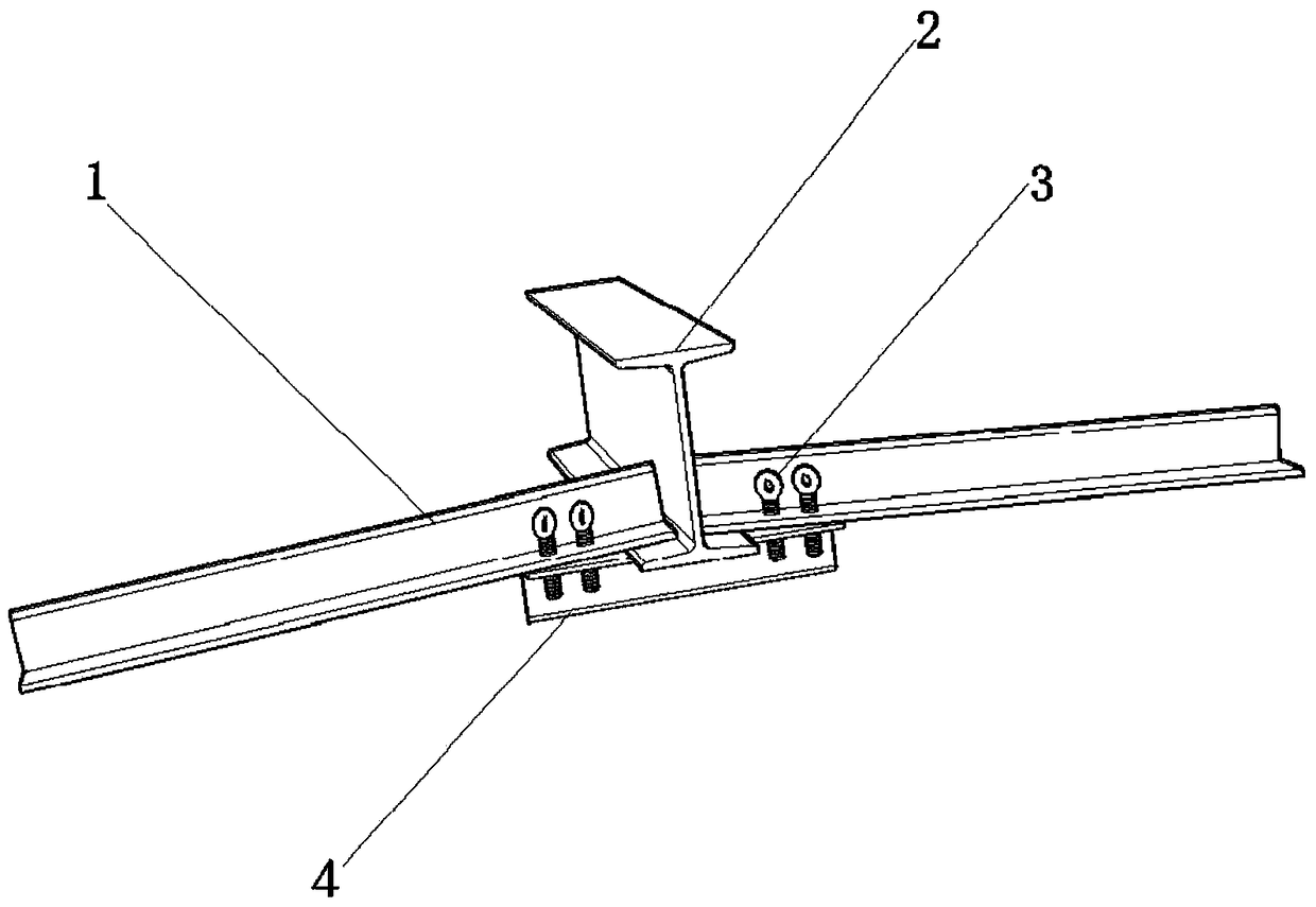
[0028] Such as figure 1 A special-shaped curved surface steel structure glass top conversion frame shown is supported under the supporting I-beam 2 of the glass top plate. The conversion frame includes a fixed angle steel 4 for the conversion frame. Both ends of the fixed angle steel 4 for the conversion frame are Eyebolts 3 are provided, and the fixed angle steel 4 of the conversion frame is connected with the horizontal load-bearing angle steel 1 of the conversion frame through the eyebolts 3. On the lower flange of steel 2.

[0029] Wherein, the length of the fixed angle steel 4 of the conversion frame is greater than the flange width of the supporting I-beam 2, the number of the eyebolts 3 on one side of the supporting I-beam 2 is 2, and the number of the eyebolts 3 on one side of the supporting I-beam 2 is two. The distance between the two eyebolts 3 on both sides and closest to the support I-beam 2 and the flange of the support I-beam 2 is 3cm, and the two adjacent eyeb...

Embodiment 2

[0039] All the other are identical with embodiment 1, difference is:

[0040] 1) The distance between the two eyebolts 3 that are located on both sides of the supporting I-beam 2 and closest to the supporting I-beam 2 and the flange of the supporting I-beam 2 is 5cm;

[0041] 2) In step 2, the length of the longitudinal load-bearing angle steel is designed according to the spacing of the transverse load-bearing angle steel 1 of the transfer frame, and its length is 1.5m.

Embodiment 3

[0043] All the other are identical with embodiment 1, difference is:

[0044] 1) The distance between the two eyebolts 3 located on both sides of the supporting I-beam 2 and closest to the supporting I-beam 2 and the flange of the supporting I-beam 2 is 1 cm;

[0045] 2) In step 2, the length of the longitudinal load-bearing angle steel is designed according to the spacing of the transverse load-bearing angle steel 1 of the transfer frame, and its length is 0.5m.


PUM

PropertyMeasurementUnit
Lengthaaaaaaaaaa
Lengthaaaaaaaaaa

Abstract

The invention provides a special-shaped hook-face steel structure glass top face conversion frame and an implementation method thereof. The problems that in the background technology, supporting is hard to conduct on a steel structure of the special-shaped hook-face steel structure glass top face, and ceiling, strong and weak electric wiring, air pipe mounting and the like cannot be constructed normally are solved. The special-shaped hook-face steel structure glass top face conversion frame and the implementation method thereof have the advantages that operating practicability is high, the working efficiency is high, and a bearing structure is not destroyed.

Description

technical field [0001] The invention relates to the field of engineering construction, in particular to a special-shaped curved surface steel structure glass top conversion frame and an implementation method. Background technique [0002] With the continuous improvement of construction technology and people's aesthetic level, steel structures are widely used in construction projects, and architectural shapes are becoming more and more novel and unique. Curves and straight lines, complexity and simplicity and other plastic arts aesthetics have been widely used in architectural design. [0003] Some buildings have a steel structure on the ground, and the roof of the building is designed as a solar photovoltaic curtain wall. In order to increase the illuminated area, the shape is designed as a curve, that is, the roof of the photovoltaic curtain wall. [0004] Since the steel structure is the main load-bearing member of the main structure, it is not allowed to weld or open hole...

Claims


Application Information

Patent Timeline
IPC IPC(8): E04B9/06
CPCE04B9/061
Inventor 刘文峰
Owner CHINA MCC17 GRP
Why Eureka
Try Eureka