Insertion loss test method and system

A technology of insertion loss and testing system, which is applied in measuring devices, measuring electrical variables, and measuring dielectric properties, etc. It can solve problems affecting the measurement accuracy of insertion loss and large loss, and achieve high test efficiency, improved accuracy, and simple connection lines Effect

Inactive Publication Date: 2018-10-12
PHICOMM (SHANGHAI) CO LTD
View PDF8 Cites 6 Cited by
  • Summary
  • Abstract
  • Description
  • Claims
  • Application Information

AI Technical Summary

Problems solved by technology

Moreover, the system also uses a power divider, which will produce a few db attenuation every time a signal is distributed, and the loss will be greater as the number of ports increases, which greatly affects the measurement accuracy of insertion loss

Method used


Image

  • Insertion loss test method and system
  • Insertion loss test method and system
  • Insertion loss test method and system

Examples


Embodiment 1

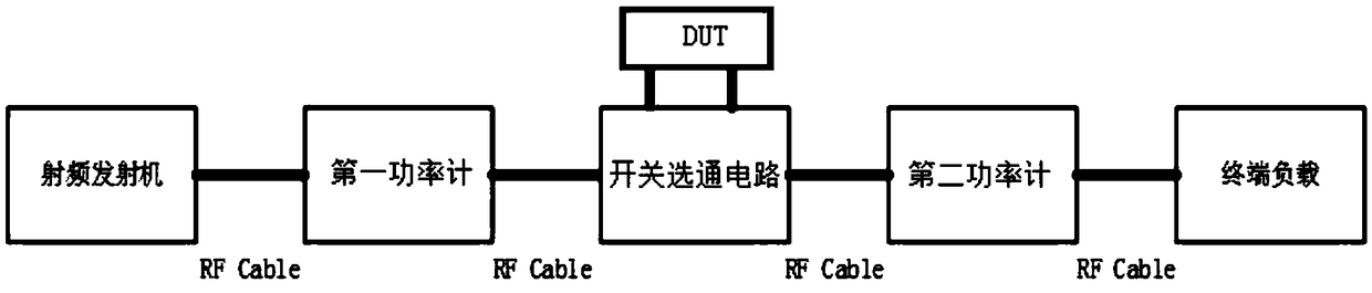
[0034] image 3 A functional block diagram of an implementation of an insertion loss testing system is shown. The insertion loss testing system includes a radio frequency transmitter, a first power meter, a second power meter, and a switch gating circuit. The radio frequency transmitter is connected to the first power meter through a radio frequency cable, and the first power meter and the second power meter are respectively connected to the switch gating circuit through a radio frequency cable, and the switch gating circuit is used for to access the device under test.

[0035]The radio frequency transmitter sends a radio frequency signal of a specific frequency band to the first power meter through a radio frequency cable, and the radio frequency transmitter mainly refers to a high-power radio frequency signal source, which is used to simulate a transmitting base station or a high-power radio station. The first power meter and the second power meter are respectively arrange...

Embodiment 2

[0046] In order to realize the online real-time synchronous processing of data collection of each part, simplify the connection line and intelligently control the insertion loss test, on the basis of the first embodiment, the system of the second embodiment also includes a control terminal and a serial port server. The control terminal is communicatively connected with the first power meter, the second power meter, and the switch gating circuit respectively via the serial port server.

[0047] Figure 5 Another embodiment of an insertion loss testing system of the present invention is shown. The control terminal can be a control computer, or other smart devices such as mobile phones and other handheld pads. The control terminal communicates with the serial port server through Ethernet, so as to control the serial port server to obtain the power values ​​(unit: W) of the first power meter and the second power meter, and perform insertion loss calculation. This is faster, more...

Embodiment 3

[0053] Figure 6 An embodiment of an insertion loss testing method of the present invention is shown. The test method is applicable to the insertion loss test system of Embodiment 1 or Embodiment 2, and the above-mentioned system is used to directly measure the insertion loss value of the device under test when it is connected to the insertion loss test system.

[0054] Specifically, the test method includes:

[0055] Step 1 S10, using the switch gating circuit to connect the device under test to the insertion loss test system;

[0056] Step 2 S20, obtain the power values ​​of the first power meter and the second power meter, and calculate the insertion loss ΔS according to the above power values 1 .

[0057] Refer to Embodiment 1 or Embodiment 2 for the example process of the specific test method.


PUM


Abstract

The invention provides an insertion loss test method and system, and belongs to the technical field of loss test. The insertion loss test system includes a radio frequency transmitter, a first power meter, a second power meter and a switch gating circuit, wherein the radio frequency transmitter is connected to the first power meter through a radio frequency cable; the first power meter and the second power meter are each connected with the switch gating switch through a radio frequency cable; the switch gating switch is used for accessing a device to be tested; and the first power meter and the second power meter are used for detecting the input and output power of the device to be tested respectively. The insertion loss test method is implemented based on the insertion loss test system, and includes the following steps: S01, inserting the device to be tested into the insertion loss test system by means of the switch gating circuit; and S02, acquiring the power values of the first power meter and the second power meter, and according to the above power values, calculating the insertion loss Delta S1. The insertion loss test method and system can realize on-line measurement of insertion loss of the device to be tested under the large power matched state of the transmitter and the load, and can also improve the test efficiency.

Description

technical field [0001] The invention relates to the technical field of loss testing, in particular to an insertion loss testing method and system. Background technique [0002] At present, there are mainly the following methods for measuring insertion loss, for example, measuring the insertion loss of the device under test through a network analyzer, or measuring the insertion loss of the device under test through a terminal power meter or a radio frequency signal source. The common problem with these methods is that they are biased towards the measurement of passive systems or are mainly suitable for the measurement of low-power radio frequency equipment. It is basically impossible to measure the insertion loss of the high-power DUT under the high-power matching state of the transmitter and the load. [0003] figure 1 It shows that an existing network analyzer performs insertion loss measurement on a device under test. The RF port of the network analyzer is connected to ...

Claims


Application Information

Patent Timeline
Patent Type & Authority Applications(China)
IPC IPC(8): G01R27/26
CPCG01R27/2694
Inventor 游少剑
Owner PHICOMM (SHANGHAI) CO LTD
Why Eureka
Try Eureka